|
|
|
|
||||||||||||||||||||||||||||||||||||||||||||||||||||||||||||||||||||||||||||||||||||||||||||||||||||||||||||||||||||||||||||||||||||||||||||||||||||||||||||||||||||||||||||||||||||||||||||||||||||||||||||||||||||||||||||||||||||||||
外形轮廓 互换性 |
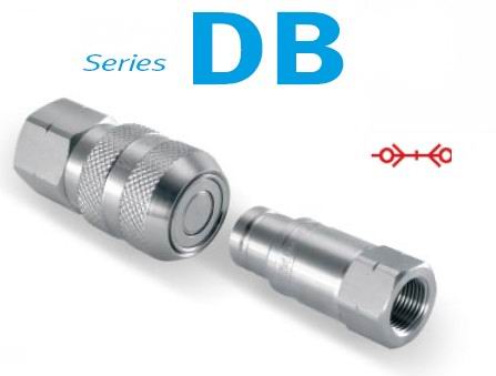
DB SERIES QUICK-RELEASE DRY-BREAK COUPLINGS 独特的设计 |
通径 |
5.5-18.5mm |
最大工作压力 |
根据通径要求,140-190bar (2030-2755 psi ) |
材料 |
316L不锈钢 密封件:氟橡胶或三元乙丙橡胶(全氟醚橡胶或根据要求选择密封材料) |
技术数据 |
球锁 自动连接 大流量 高温性能(全氟醚橡胶密封) |
应用 |
石油化工 制药 化妆品 食品处理 抗流体冲击和抗腐蚀 |
Standard Materials:
Sockets:
| Part Number | Nominal Diameter | End Connection | Thread Detail | Seal Material |
| 2DBS-25F | 1/4" | Female Thread | 1/4-18 NPTF | Viton |
| 2DBS-25F192 | 1/4" | Female Thread | 1/4-18 NPTF | EPDM |
| 2DBS-25FBS | 1/4" | Female Thread | 1/4-19 BSPP | Viton |
| 2DBS-25FBS192 | 1/4" | Female Thread | 1/4-19 BSPP | EPDM |
| 3DBS-37F | 3/8" | Female Thread | 3/8-18 NPTF | Viton |
| 3DBS-37F192 | 3/8" | Female Thread | 3/8-18 NPTF | EPDM |
| 3DBS-37FBS | 3/8" | Female Thread | 3/8-19 BSPP | Viton |
| 3DBS-37FBS192 | 3/8" | Female Thread | 3/8-19 BSPP | EPDM |
| 4DBS-50F | 1/2" | Female Thread | 1/2-14 NPTF | Viton |
| 4DBS-50F192 | 1/2" | Female Thread | 1/2-14 NPTF | EPDM |
| 4DBS-50FBS | 1/2" | Female Thread | 1/2-14 BSPP | Viton |
| 4DBS-50FBS192 | 1/2" | Female Thread | 1/2-14 BSPP | EPDM |
| 6DBS-75F | 3/4" | Female Thread | 3/4-14 NPTF | Viton |
| 6DBS-75F192 | 3/4" | Female Thread | 3/4-14 NPTF | EPDM |
| 6DBS-75FBS | 3/4" | Female Thread | 3/4-14 BSPP | Viton |
| 6DBS-75FBS192 | 3/4" | Female Thread | 3/4-14 BSPP | EPDM |
| 8DBS-100F | 1" | Female Thread | 1-11 1/2 NPTF | Viton |
| 8DBS-100F192 | 1" | Female Thread | 1-11 1/2 NPTF | EPDM |
| 8DBS-100FBS | 1" | Female Thread | 1-11 BSPP | Viton |
| 8DBS-100FBS192 | 1" | Female Thread | 1-11 BSPP | EPDM |
Plugs:
| Part Number | Nominal Diameter | End Connection | Thread Detail | Seal Material |
| 2DBP-25F | 1/4" | Female Thread | 1/4-18 NPTF | Viton |
| 2DBP-25F192 | 1/4" | Female Thread | 1/4-18 NPTF | EPDM |
| 2DBP-25FBS | 1/4" | Female Thread | 1/4-19 BSPP | Viton |
| 2DBP-25FBS192 | 1/4" | Female Thread | 1/4-19 BSPP | EPDM |
| 3DBP-37F | 3/8" | Female Thread | 3/8-18 NPTF | Viton |
| 3DBP-37F192 | 3/8" | Female Thread | 3/8-18 NPTF | EPDM |
| 3DBP-37FBS | 3/8" | Female Thread | 3/8-19 BSPP | Viton |
| 3DBP-37FBS192 | 3/8" | Female Thread | 3/8-19 BSPP | EPDM |
| 4DBP-50F | 1/2" | Female Thread | 1/2-14 NPTF | Viton |
| 4DBP-50F192 | 1/2" | Female Thread | 1/2-14 NPTF | EPDM |
| 4DBP-50FBS | 1/2" | Female Thread | 1/2-14 BSPP | Viton |
| 4DBP-50FBS192 | 1/2" | Female Thread | 1/2-14 BSPP | EPDM |
| 6DBP-75F | 3/4" | Female Thread | 3/4-14 NPTF | Viton |
| 6DBP-75F192 | 3/4" | Female Thread | 3/4-14 NPTF | EPDM |
| 6DBP-75FBS | 3/4" | Female Thread | 3/4-14 BSPP | Viton |
| 6DBP-75FBS192 | 3/4" | Female Thread | 3/4-14 BSPP | EPDM |
| 8DBP-100F | 1" | Female Thread | 1-11 1/2 NPTF | Viton |
| 8DBP-100F192 | 1" | Female Thread | 1-11 1/2 NPTF | EPDM |
| 8DBP-100FBS | 1" | Female Thread | 1-11 BSPP | Viton |
| 8DBP-100FBS192 | 1" | Female Thread | 1-11 BSPP | EPDM |
ML6DBS75FBS
ML6DBS75FBS292
ML6DBS75FBS242
ML6DBS75FBS503
ML8DBS100FBS
ML8DBS100FBS292
ML8DBS100FBS242
ML8DBS100FBS503
ML2DBS25FBS
ML2DBS25FBS292
ML2DBS25FBS242
ML2DBS25FBS503
ML2DBS25F
ML2DBS25F292
ML2DBS25F242
ML2DBS25F503
ML8DBS100F
ML8DBS100F292
ML8DBS100F242
ML8DBS100F503
ML4DBS50F
ML4DBS50F292
ML4DBS50F242
ML4DBS50F503
ML8DBP100F
ML8DBP100F292
ML8DBP100F242
ML8DBP100F503
ML6DBS75F
ML6DBS75F292
ML6DBS75F242
ML6DBS75F503
ML2DBS93
2DBSG143
2DBSG292
2DBSG242
2DBSG503
2DBPG143
2DBPG292
2DBPG242
2DBPG503
6DBPG143
6DBPG292
6DBPG242
6DBPG503
ML4DBS50FBS
ML4DBS50FBS292
ML4DBS50FBS242
ML4DBS50FBS503
Part Number Part Number***
Blue CR12FFSLB Blue CR12FFPLB
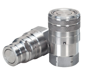
Eaton MLDB Series stainless steel coupling is a flat face dry break coupling
There’s a certain energy at Eaton. It’s the power of integrating the competencies of some of the world’s most respected names to build a brand you can trust to meet every power management need. The energy created supports our commitment to powering business worldwide.
As the world’s demand increases for high-efficiency hydraulic systems for mobile and stationary applications, Eaton is helping to solve these challenges more reliably, efficiently, and sustainably. Our goal is simple; to provide unique solutions across a wide range of markets that keep businesses on the leading edge of change. Visit Eaton.com/hydraulics/fusion.
That’s the power of Eaton.
Serving eight key segments - sharing one focus
Alternative Energy
Making energy sources technically practical and economically sound requires the kind of control made possible by high-quality components. When Eaton is on the inside, you will experience the reliable, consistent performance to create and capture energy— making renewable energy an every-day energy.
Agriculture & Forestry
There’s a reason farming and forestry are called “working the land.” These segments involve some of the hardest work and longest hours of any sector in the economy. Your productivity and profitability depend on the way you manage time and tasks.
Discrete Manufacturing
Produce at peak efficiency with the superior precision and repeatability of Eaton products. Eaton hydraulic components provide the precise control and consistent operation required for virtually every step in your manufacturing operation. With Eaton, we’ll help you redefine the meaning of raw productivity.
Commercial Vehicles
Eaton technologies can make your driving operation more successful. Greater comfort and productivity help increase driver retention, while reduced emissions, leaks, and noise improve environmental performance. Increased efficiencies overall mean lower costs and higher net revenue.
Oil & Gas
As the oil & gas industry continues to face further globalization and consolidation, large-scale organizations that can meet your needs in every corner of the world are more difficult to find. At Eaton, our portfolio of products is only surpassed by our tremendous reach.
Material Handling
Eaton hydraulic systems provide the precise control and consistent operation required for material handling and utility work. With a broad selection of products and solutions built in, Eaton helps make you a master of your domain.
Eaton is a leading diversified
power management company
Processing
Whatever your industry, no matter which processes you manage, Eaton parts and systems help keep you up and running. Our components make equipment more efficient and easier to use, so you get optimal machine performance and maximum productivity.
Construction & Mining
When you work on a large scale, even the details are big. You need to trust every part of the equipment that lets you handle construction and mining jobs. For reliable components that deliver consistent performance in extreme conditions, turn to Eaton.
Eaton provides reliable, efficient and safe power management for a growing number of industries.
Understanding and helping our customers succeed
.
Listening and understanding to requirements and
business drivers
.
Delivering solutions with value propositions to solve the
critical business needs
Knowing what’s important to our customers and integrating that knowledge into the fabric of our business
.
…to deliver innovative, quality products
.
…to respond fast
.
…to provide dedicated customer service and support
around the globe
Our strength is global reach with local responsiveness and support
.
Customers served in more than 150 countries
.
Diverse channels ensure reliable availability and support
.
Design and engineering teams provide support for
standard products and custom solutions
.
Eaton experts offer efficient product and application
training
Table of Contents
Overview ......................................................................... 2
How to Order ...................................................................... 4
Safety Information .................................................................. 5
Fluid Transfer and Hydraulic
MLDB Series: Stainless Steel Flat Face/Dry Break ......................................... 6
MLFF Series: ISO 16028 Stainless Steel Flat Face/Dry Break................................. 8
FFCUP Series: ISO 16028 Connect Under Pressure Flat Face Plug/Male....................... 10
FF Series: ISO 16028 Interchange Steel .................................................12
Comparison Chart.................................................................. 18
Eaton Quick Disconnect Couplings – Customizing Solutions for the Future… Hydraulics and Beyond
For over 50 years, Eaton has continued to manufacture and supply the highest performing quick disconnect couplings globally for many different market segments including agriculture, construction, transportation, and fire and rescue just to name a few. Eaton’s quality and performance have never been compromised when it comes to engineering and manufacturing its full line of quick disconnect couplings. From traditional industry standards to custom couplings for the next generation of emerging markets and new advanced technologies, Eaton continues to provide quick disconnect coupling solutions to meet your demands.
Custom Design Capability – One Application at a Time
Eaton continues the tradition of developing custom quick disconnect couplings for customers that need a product to perform above and beyond industry standards. Whether it is a custom coupling for the world’s most powerful and sophisticated super computers that use electronic cooling or a self contained breathing apparatus coupling for first responders, Eaton has the ability to work directly with you on a solution. Contact Eaton to see how our dedicated and experienced design engineering team will work with you to develop a quick disconnect coupling solution.
How to Order
Eaton Quick Disconnect Couplings can be ordered as separate Caution: halves. For special packaging, contact Eaton. Standard cou-
The user should carefully observe the precautions listed
pling part numbers are described below.
in this catalog. These include selection of seals and body materials for fluid compatibility and recommendations on
Dimensions
the selection of quick disconnect couplings. In addition,
Dimensions in this catalog are for reference only. Actual
dimensions may vary from those shown. care should be taken not to exceed the maximum operat-ing pressures listed for each coupling size and type shown
Coupling Identification
in the physical characteristics table for each coupling. Generally, the coupling series or complete part number will be Because of possible variations in machining tolerances, stenciled on the coupling body.
quality control, inspection and quality assurance, Eaton coupling halves should not be used with coupling halves supplied by other manufacturers except where such use is approved for a particular coupling as noted in this catalog or specifically by Eaton.
Safety Information
1.0 General Instructions.
1.1 Scope. The scope of this safety bulletin is to warn against improper selection, use, installation, etc. of Eaton coupling products.
1.2 Distribution. A copy of this safety bulletin should be distributed to all individuals responsible for using and/or selecting Eaton coupling products.
1.3 Fail-Safe. Design all systems and equipment for fail-safe operation such that failure of any component does not result in personal injury and/or property damage.
1.4 User Responsibility. It is the sole responsibility of the user to select and determine that the Eaton product is compatible with the end use application. The user is responsible for reading and following this safety bulletin as well as any instructions or literature on the Eaton product being used. The user must provide necessary product warnings for Eaton couplings products, used with systems or equipment, to the operators of the systems or equipment.
1.5
Usage with other Manufacturers’ Products. When using Eaton coupling products with other manufacturers’ adapters, hoses, etc., do not exceed the lowest pressure rating of any of the components being used or rupture may result.
2.0
Selection of Eaton Couplings.
2.1 Pressure. Ensure that the maximum operating pressure of the system or equipment does not exceed the rated operating pressure of the Eaton coupling product or rupture may result.
2.2 Fluid Compatibility. Verify that all components (seals, metals, etc.) are compatible with the fluid being conveyed. Failure to do so may result in high speed fluid discharge and/or leakage of fluids which may be flammable, toxic, at extreme temperatures, or otherwise harmful.
2.3 Temperature. Ensure that the maximum operating temperature of the system or equipment does not exceed the rated operating temperature of the Eaton coupling product (including seals) or rupture may result.
2.4 Coupling Size. Use properly sized couplings such that there is not a large pressure drop across them thus avoiding system damage due to excessive heat generation or failure of internal components.
2.5 Sleeve Lock. Use sleeve locks or threaded couplings where there is the possibility of accidental disconnection. Failure to utilize sleeve locks or threaded couplings in these applications may result in hose whip, expelled components, high speed fluid discharge, system damage, or leakage of fluids which may be flammable, toxic, at extreme temperatures, or otherwise harmful.
2.6 Connect or Disconnect Under Pressure. If connection and/or disconnection of couplings under pressure is a requirement, only use couplings designed for connection/disconnection under pressure. Failure to utilize this type of coupling in that application may result in hose whip, expelled components, high speed fluid discharge, and/or system damage. Be certain not to confuse the rated operating pressure with the rated connect/disconnect under pressure.
2.7 Environment. Ensure that Eaton couplings are compatible with the surrounding environment. The surrounding environment may be heat, salt water, moisture, chemicals, and the like. Failure to protect against an adverse environment may cause system damage, premature failure, and/or leakage of fluids which may be flammable, toxic, at extreme temperatures, or otherwise harmful.
2.8 External Loads. Avoid any external loads such as side loads, tensile loads, vibration, etc. Failure to do so may result in accidental disconnection, premature failure, system damage, and/or leakage of fluids which may be flammable, toxic, at extreme temperatures, or otherwise harmful.
2.9
Welding & Brazing. Extreme heating of plated products above +450°F (+232°C) such as welding, brazing, baking, etc., where the plating is burned off, may result in the release of deadly gases.
3.0
Installation of Eaton Couplings.
3.1 Inspection of Product. Prior to installation, ensure that the Eaton product meets all of the requirements of the system and/or equipment it is to be used on. Ensure you have the correct part number, function test the coupling by connecting it with a mating half. The function test should result in smooth, non-binding operation or premature failure may result.
3.2 Cleanliness. Use end caps and plugs to reduce the risk of system contamination or damage to critical sealing surfaces. Failure to do so may result in leakage of fluids which may be flammable, toxic, at extreme temperatures, or otherwise harmful. Caps and plugs are not a secondary seal unless explicitly noted.
3.3
Location. Place Eaton couplings in a safe location such as not to expose the user to personal injury (slippage, tripping, falling, etc.) during installation, connection, disconnection and maintenance.
4.0
Product Maintenance. A maintenance schedule should be put in place to ensure that Eaton couplings are functioning properly. Eaton is not responsible for product failures resulting from modification or improper maintenance.
4.1 Inspection. Visually inspect to ensure that there is no leakage, cracked components, corrosion build-up, contamination build-up, wear, etc. If any abnormality is encountered, the coupling should be replaced immediately.
The Eaton MLDB Series stainless steel coupling is a flat face/dry break coupling used for fluid transfer applications. The new and improved design offers the ability to connect with less force, higher sealing performance and are available in multiple configurable end connections.
. Designed and manufactured in . Capable of working under high . Designed with higher flow accordance with Article 3.3 of the temperature applications capacity and resistance to European Pressure Equipment aggressive fluids and corrosion
. Shock resistant color coding ring
Directive (PED) 97/23 EC
option available in 1/2” size . Standard body material-316/316L
. Safety sleeve lock prevents Stainless steel corrosion resistant
. Serviceable design allows for
accidental disconnections
easy cleaning and seal . Standard seal material: FKM,
. Push to connect with double replacement EPDM, Kalrez. and generic FFKM shut-off valving
Physical Characteristics
Nominal Maximum
Body Flow Operating Rated*
Size Diameter Pressure Flow Air Inclusion Fluid Loss Force to Connect
(mm) bar (psi) L/min (gpm) ml-cc. ml-cc. N lbf
1/4 5.9 25 360 15 4 0.002 0.001 85 19
3/4 15 25 360 120 32 0.030 0.050 170 38
Applications & Markets Flow rate (l/min) 1 10 100 1000 5
. Process/Fluid transfer 72.5
4
. Cooling
3
. Corrosive environments
2
.
Chemicals/Petrochemicals
.
Pharmaceuticals
. Food processing
. Electrical
0.5
0.3
0.2
1.45
0.1
Flow rate (gpm)
Test Fluid: Oil viscosity 30 cSt at 40°C/104°F
The former DB series interchanges with the new MLDB series, however close attention is requested to the
differences in performance. Eaton recommends to connect an MLDB plug(male) with an MLDB socket(female).
Seal Elastomer Data*
Pressure drop (bar)
Seal Elastomer Max. Operation Temperature Range
FKM (Fluorocarbon) -20°C +200°C/-4°F +392°F
EPDM (Ethylene-Propylene) -40°C +150°C/-40°F +302°F
Kalrez. 6375 -20°C +275°C/-4°F +527°F
Generic FFKM (Perfluorocarbon) -15°C +275°C/+5°F +527°F
MLDB Series
Stainless Steel Flat Face/Dry Break
Sockets(Female)
Part Number Thread Size*(Female) Dimensions
FKM EPDM Kalrez. 6375 Generic FFKM Body Size NPT BSPP Fig. A (in) B (in) C (in) Hex (in) A (mm) B (mm) C (mm) Hex (mm) lbs grams
ML2DBS25FBS ML2DBS25FBS292 ML2DBS25FBS242 ML2DBS25FBS503 1/4 – 1/4-19 1 1.79 1.06 0.96 0.87 45.4 26.8 24.5 22 0.26 116
ML2DBS25F ML2DBS25F292 ML2DBS25F242 ML2DBS25F503 1/4 1/4-18 1 1.73 1.06 0.96 0.87 43.9 26.8 24.5 22 0.26 116
ML4DBS50FBS ML4DBS50FBS292 ML4DBS50FBS242 ML4DBS50FBS503 1/2 – 1/2-14 1 2.44 1.5 1.4 1.26 61.9 38.2 35.5 32 0.73 330
ML4DBS50F ML4DBS50F292 ML4DBS50F242 ML4DBS50F503 1/2 1/2-14 1 2.44 1.5 1.4 1.26 61.9 38.2 35.5 32 0.73 330
ML6DBS75FBS ML6DBS75FBS292 ML6DBS75FBS242 ML6DBS75FBS503 3/4 – 3/4-14 1 3.02 1.89 1.83 1.61 76.8 47.9 46.5 41 1.34 610
ML6DBS75F ML6DBS75F292 ML6DBS75F242 ML6DBS75F503 3/4 3/4-14 1 3.02 1.89 1.83 1.61 76.8 47.9 46.5 41 1.34 610
ML8DBS100FBS ML8DBS100FBS292 ML8DBS100FBS242 ML8DBS100FBS503 1 – 1-11 1 3.54 2.26 2.16 1.97 89.9 57.4 54.9 50 2.31 1050
ML8DBS100F ML8DBS100F292 ML8DBS100F242 ML8DBS100F503 1 1-11 1/2 1 3.42 2.26 2.16 1.97 86.9 57.4 54.9 50 2.31 1050
*Alternative end connections available upon request. To obtain connected length of coupling, add dimensions A (Fig. 1) and G (Fig. 2) together.
Plugs(Male)
Part Number Thread Size*(Female) Dimensions
FKM EPDM Kalrez. 6375 Generic FFKM Body Size NPT BSPP Fig. D (in) E (in) F (in) G (in) Hex (in) D (mm) E (mm) F (mm) G (mm) Hex (mm) lbs grams
ML2DBP25FBS ML2DBP25FBS292 ML2DBP25FBS242 ML2DBP25FBS503 1/4 – 1/4-19 2 1.72 0.65 0.96 1.31 0.87 43.6 16.5 24.5 33.2 22 0.17 78
ML2DBP25F ML2DBP25F292 ML2DBP25F242 ML2DBP25F503 1/4 1/4-18 2 1.66 0.65 0.96 1.25 0.87 42.1 16.5 24.5 31.7 22 0.17 78
ML4DBP50FBS ML4DBP50FBS292 ML4DBP50FBS242 ML4DBP50FBS503 1/2 – 1/2-14 2 2.39 0.99 1.4 1.8 1.26 60.7 25.2 35.5 45.7 32 0.46 210
ML4DBP50F ML4DBP50F292 ML4DBP50F242 ML4DBP50F503 1/2 1/2-14 2 2.39 0.99 1.4 1.8 1.26 60.7 25.2 35.5 45.7 32 0.46 210
ML6DBP75FBS ML6DBP75FBS292 ML6DBP75FBS242 ML6DBP75FBS503 3/4 – 3/4-14 2 2.97 1.29 1.83 2.11 1.61 75.5 32.8 46.5 53.6 41 0.87 395
ML6DBP75F ML6DBP75F292 ML6DBP75F242 ML6DBP75F503 3/4 3/4-14 2 2.97 1.29 1.83 2.11 1.61 75.5 32.8 46.5 53.6 41 0.87 395
ML8DBP100FBS ML8DBP100FBS292 ML8DBP100FBS242 ML8DBP100FBS503 1 – 1-11 2 3.52 1.59 2.16 2.60 1.97 89.4 40.4 54.9 66.1 50 1.54 700
ML8DBP100F ML8DBP100F292 ML8DBP100F242 ML8DBP100F503 1 1-11 1/2 2 3.4 1.59 2.16 2.48 1.97 86.4 40.4 54.9 63.1 50 1.54 700
*Alternative end connections available upon request.
To obtain connected length of coupling, add dimensions A (Fig. 1) and G (Fig. 2) together.
Seal Kit and Tool for Servicing Sockets (Female)
Seal Kit Part Number (includes 5 sets) Seal Kit Part Number (includes 1 set) Body Size Tool Part Number FKM EPDM Kalrez. 6375 Generic FFKM
1/4 ML2DBS93 2DBSG143 2DBSG292 2DBSG242 2DBSG503
3/4 ML6DBS93 6DBSG143 6DBSG292 6DBSG242 6DBSG503
For installation instructions, please contact your Eaton sales representative.
Seal Kit for Servicing Plugs (Male)
Seal Kit Part Number (includes 5 sets) Seal Kit Part Number (includes 1 set) Body Size FKM EPDM Kalrez. 6375 Generic FFKM
1/4 2DBPG143 2DBPG292 2DBPG242 2DBPG503
3/4 6DBPG143 6DBPG292 6DBPG242 6DBPG503
For installation instructions, please contact your Eaton sales representative. No tool required for servicing of the plug(male).
Color Coding Ring Option*
Socket/Female Ring** Plug/Male Ring** Tool & Rings Kit Body Size Color Part Number Color Part Number Tool Part Number Part Number***
Blue CR12FFSLB Blue CR12FFPLB
CR4DBSP93
CRKIT4DB
Yellow CR12FFSYL Yellow CR12FFPYL
*For requests on other sizes, alternative colors or installation instructions, please contact your Eaton sales representative.
**Orders must be in multiples of 10 pcs.
***The kit consists of a tool plus 10 socket rings and 10 plug rings of each color.
MLFF Series
The Eaton MLFF Series stainless steel coupling is a flat face dry break coupling used for hydraulic applications. The MLFF series interchanges with all ISO 16028 profiles. Due to its stainless steel design, it is corrosion resistant and can handle aggressive environments.
. Designed and manufactured . Shock resistant color coding ring . Alternative end connections under Article 3.3 of the European option available in sizes 10FF, available upon request Pressure Equipment Directive 12FF, 16FF and 25FF to prevent
. Standard seal material: FKM,
(PED) 97/23 EC accidental crossing of lines EPDM, NBR+AU
. Safety sleeve lock prevents . Resistant to aggressive . Utilize FF Series dust caps
accidental disconnections environments and corrosion
. Push to connect with double . Standard body material—316L shut-off valving Stainless steel corrosion resistant
Physical Characteristics
Maximum Operating Pressure Minimum Burst Pressure
ISO Coupling Plug/ Socket/ Plug/ Socket/ Fluid Air
Size* Size Connected Male Half Female Half Connected Male Half Female Half Rated Flow** Loss Inclusion Force to Connect
(mm) bar (psi) bar (psi) bar (psi) bar (psi) bar (psi) bar (psi) L/min. (gpm) ml-cc. ml-cc. N Lbs
6.3 1/4” 250 3625 250 3625 250 3625 2335 33858 1640 23780 1330 19285 17 4.49 0.004 0.007 80 18.0
12 1/2” 250 3625 250 3625 250 3625 1679 24346 997 14457 993 14399 55 14.53 0.012 0.013 195 43.8
19 3/4” 250 3625 250 3625 250 3625 1370 19865 882 12789 845 12253 105 27.74 0.034 0.015 215 48.3
– 1”1/2 230 3335 230 3335 80 1160 800 11600 700 10150 320 4640 270 71.32 0.050 – 580 130.4
*The ISO size corresponds to the internal diameter of the hose or the external diameter of the rigid tube (as defined in ISO 4397 Standard)
**Indicated values refer to a 1 bar/14.5 psi pressure drop
Applications & Markets Flow rate (l/min)
1 10 100 1000
72.5
5
. Construction
58.0
4
. Agriculture 43.5
3
. Iron and Steel Industry 29.0
2
. Railway
. Oil and Gas
14.5
.
Marine
.
Material Handling
7.25
0.5
. General Hydraulic applications
4.35
0.3
0.2
2.90
1.45
0.1
Flow rate (gpm)
Test Fluid: Oil viscosity 30 cSt at 40°C/104°F
Seal Elastomer Data*
Pressure drop (bar)
ISO Size (6FF to 25FF) Non-ISO Size (40FF and 50FF)
Maximum Operation Maximum Operation
Seal Elastomer P/N Code Temperature Range Temperature Range
NBR (Nitrile) + AU (Polyurethane) -25°C +100°C/-13°F +212°F on request
FKM (Fluorocarbon) -143 -20°C +200°C/-4°F +392°F -15°C +180°C/+5°F +356°F
EPDM (Ethylene-Propylene) -192 -40°C +150°C/-40°F +302°F on request
MLFF Series
ISO 16028 Stainless Steel Flat Face/Dry Break
Sockets(Female)
Nominal Flow Part Number ISO Size Diameter Thread Size*(Female) Dimensions Weight
NBR+AU FKM EPDM Body Size (mm) NPT BSPP Fig. A (in) B (in) C (in) Hex (in) A (mm) B (mm) C (mm) Hex (mm) lbs grams
ML6FFS25 ML6FFS25143 ML6FFS25192 1/4 6.3 6 1/4-18 – 1 ML6FFS25BS ML6FFS25BS143 ML6FFS25BS192 1/4 6.3 6 – 1/4-19 1 ML10FFS37 ML10FFS37143 ML10FFS37192 3/8 10 8.6 3/8-18 – 1 ML10FFS37BS ML10FFS37BS143 ML10FFS37BS192 3/8 10 8.6 – 3/8-19 1 ML10FFS50BS ML10FFS50BS143 ML10FFS50BS192 3/8 10 8.6 – 1/2-14 1 ML12FFS50 ML12FFS50143 ML12FFS50192 1/2 12.5 11 1/2-14 – 1 ML12FFS50BS ML12FFS50BS143 ML12FFS50BS192 1/2 12.5 11 – 1/2-14 1 ML12FFS75BS ML12FFS75BS143 ML12FFS75BS192 1/2 12.5 11 – 3/4-14 1 ML16FFS75 ML16FFS75143 ML16FFS75192 5/8 16 13 3/4-14 – 1 ML16FFS75BS ML16FFS75BS143 ML16FFS75BS192 5/8 16 13 – 3/4-14 1 ML19FFS75 ML19FFS75143 ML19FFS75192 3/4 19 15 3/4-14 – 1 ML19FFS75BS ML19FFS75BS143 ML19FFS75BS192 3/4 19 15 – 3/4-14 1 ML19FFS100 ML19FFS100143 ML19FFS100192 3/4 19 15 1”11.5 – 1 ML19FFS100BS ML19FFS100BS143 ML19FFS100BS192 3/4 19 15 – 1-11 1 ML25FFS100BS ML25FFS100BS143 ML25FFS100BS192 1 25 18 – 1-11 1 ML25FFS125 ML25FFS125143 ML25FFS125192 1 25 18 1”1/4 11.5 – 1
–
ML40FFS150143 – 1 1/2 – – 1”1/2 11.5 – 1
–
ML50FFS200143 – 2 – – 2” 11” – 1
*Alternative end connections available upon request.
To obtain connected length of coupling, add dimensions A (Fig. 1) and G (Fig. 2) together.
Plugs(Male)
Nominal Flow Part Number ISO Size Diameter Thread Size*(Female) Dimensions
2.13 1.06 0.94 0.87 54 27 24 22 0.30 135
2.13 1.06 0.94 0.87 54 27 24 22 0.30 135
2.68 1.26 1.16 1.06 68 32 29.5 27 0.54 245
2.68 1.26 1.16 1.06 68 32 29.5 27 0.54 245
2.80
1.26 1.16 1.06 71 32 29.5 27 0.53 240
3.27
1.50 1.56 1.42 83 38 39.5 36 1.03 470
3.27 1.50 1.56 1.42 83 38 39.5 36 1.03 470
3.39 1.50 1.56 1.42 86 38 39.5 36 1.01 460
3.39 1.66 1.56 1.42 86 42 39.5 36 1.21 550
3.39 1.66 1.56 1.42 86 42 39.5 36 1.21 550
3.82 1.81 1.77 1.61 97 46 45 41 1.69 770
3.82 1.81 1.77 1.61 97 46 45 41 1.69 770
3.80 1.82 1.77 1.61 97 46 45 41 1.56 710
3.82
1.81 1.77 1.61 97 46 45 41 1.56 710
4.07
2.36 2.36 2.17 104 60 60 55 2.83 1290
4.07
2.36 2.36 2.17 104 60 60 55 2.83 1290
5.21
3.15 2.83 2.56 132 80 72 65 6.39 2910
6.17
3.94 3.48 3.15 157 100 88.5 80 11.49 5230
Fig. 2
Weight
NBR+AU FKM EPDM Body Size (mm) NPT BSPP Fig. D (in) E (in) F (in) G (in) Hex (in) D (mm) E (mm) F (mm) G (mm) Hex (mm) lbs grams
ML6FFP25 ML6FFP25143 ML6FFP25192 1/4 6.3 6 1/4” 18 – 2 2.01 0.46 0.94 1.58 .87 51 11.6 24 40.1 22 0.20 90 ML6FFP25BS ML6FFP25BS143 ML6FFP25BS192 1/4 6.3 6 – 1/4-19 2 2.01 0.46 0.94 1.58 0.87 51 11.6 24 40.1 22 0.20 90 ML10FFP37 ML10FFP37143 ML10FFP37192 3/8 10 8.6 3/8-18 – 2 2.56 0.78 1.16 1.97 1.06 65 19.7 29.5 50 27 0.33 150 ML10FFP37BS ML10FFP37BS143 ML10FFP37BS192 3/8 10 8.6 – 3/8-19 2 2.56 0.78 1.16 1.97 1.06 65 19,7 29.5 50 27 0.33 150 ML10FFP50BS ML10FFP50BS143 ML10FFP50BS192 3/8 10 8.6 – 1/2-14 2 2.68 0.78 1.16 2.09 1.06 68 19,7 29.5 53 27 0.33 150 ML12FFP50 ML12FFP50143 ML12FFP50192 1/2 12.5 11 1/2-14 – 2 2.72 0.96 1.56 2.05 1.42 69 24.5 39.5 52 36 0.61 275 ML12FFP50BS ML12FFP50BS143 ML12FFP50BS192 1/2 12.5 11 – 1/2-14 2 2.72 0.96 1.56 2.05 1.42 69 24.5 39.5 52 36 0.64 290 ML12FFP75BS ML12FFP75BS143 ML12FFP75BS192 1/2 12.5 11 – 3/4-14 2 2.83 0.96 1.56 2.17 1.42 72 24.5 39.5 55 36 0.61 275 ML16FFP75 ML16FFP75143 ML16FFP75192 5/8 16 13 3/4” 14 -2 2.83 1.06 1.56 1.42 1.42 72 27 39.5 36 36 0.69 315 ML16FFP75BS ML16FFP75BS143 ML16FFP75BS192 5/8 16 13 – 3/4-14 2 2.83 1.06 1.56 1.42 1.42 72 27 39.5 36 36 0.69 315 ML19FFP75 ML19FFP75143 ML19FFP75192 3/4 19 15 3/4-14 – 2 3.70 1.18 1.77 2.83 1.61 94 29.9 45 72 41 1.28 580 ML19FFP75BS ML19FFP75BS143 ML19FFP75BS192 3/4 19 15 – 3/4-14 2 3.70 1.18 1.77 2.83 1.61 94 29.9 45 72 41 1.28 580 ML19FFP100 ML19FFP100143 ML19FFP100192 3/4 19 15 1” 11.5 – 2 3.70 1.18 1.77 2.83 1.61 94 29.9 45 72 41 1.13 515 ML19FFP100BS ML19FFP100BS143 ML19FFP100BS192 3/4 19 15 – 1-11 2 3.70 1.18 1.77 2.83 1.61 94 29.9 45 72 41 1.12 510 ML25FFP100BS ML25FFP100BS143 ML25FFP100BS192 1 25 18 – 1-11 2 4.12 1.42 2.36 2.17 2.17 104.6 36 60 55 55 2.37 1080 ML25FFP125 ML25FFP125143 ML25FFP125192 1 25 18 1”1/4 11.5 – 2 4.12 1.42 2.36 2.17 2.17 104.6 36 60 55 55 2.37 1080
–
ML40FFP150143 – 1 1/2 – – 1”1/2 11.5 – 2 4.37 2.25 2.99 2.76 2.76 111 57.1 76 70 70 4.15 1890
–
ML50FFP200143 – 2 – – 2” 11 – 2 4.87 2.87 3.29 2.95 2.95 123.8 72.9 83.5 75 75 5.03 2290
*Alternative end connections available upon request.
To obtain connected length of coupling, add dimensions A (Fig. 1) and G (Fig. 2) together.
Color Coding Ring Option*
Socket/Female Ring Part Number** Plug/Male Ring Part Number** Tool Tool & Rings Kit Body Size ISO Size Size Blue Red Yellow Green Blue Red Yellow Green Part Number Part Number***
3/8 10 ML10FF CR10FFSLB CR10FFSRD CR10FFSYL CR10FFSDG CR10FFPLB CR10FFPRD CR10FFPYL CR10FFPDG CR10FFSP93 CRKIT10FF
1/2 12.5 ML12FF CR12FFSLB CR12FFSRD CR12FFSYL CR12FFSDG CR12FFPLB CR12FFPRD CR12FFPYL CR12FFPDG CR12FFSP93 CRKIT12FF
5/8 16 ML16FF CR16FFSLB CR16FFSRD CR16FFSYL CR16FFSDG CR16FFPLB CR16FFPRD CR16FFPYL CR16FFPDG CR16FFSP93 CRKIT16FF
3/4 19 ML19FF CR19FFSLB CR19FFSRD CR19FFSYL CR19FFSDG CR19FFPLB CR19FFPRD CR19FFPYL CR19FFPDG CR19FFSP93 CRKIT19FF
*For requests on alternative colors or installation instructions, please contact your Eaton sales representative.
**Orders must be in multiples of 10 pcs.
***The kit consists of a tool plus 10 socket rings and 10 plug rings of each color.
FFCUP Series
ISO 16028 Connect Under Pressure Flat Face Plug/Male
The Eaton FFCUP Series plug/male coupling is an ISO 16028 standard interchange. The flush face design prevents fluid loss on disconnection and air inclusion on connection guaranteeing excellent flow capability. An integrated patented system allows the Eaton FFCUP series plug to be connected to a
Product Features
.
Designed and manufactured in
accordance with Article 3.3 of the European Pressure Equipment Directive (PED) 97/23 EC
.
Meets dimensional requirements
of ISO 16028
.
Push to connect
Physical Characteristics
Nominal Maximum
Body ISO Flow Operating
Size Size* Diameter Pressure
socket/female half coupling under 350 bar(5075 psi) residual pressure.
.
Connect under residual pressure . Alternative end connections
available upon request
.
Shock resistant color coding ring option available to prevent . Standard seal material: NBR+AU accidental crossing of lines
. Utilize FF Series dust caps
.
Standard body material—High
resistance carbon steel with zinc
trivalent plating and QPQ finish,
ROHS compliant
Minimum Burst Rated Pressure Flow** Air Inclusion Fluid Loss Force to Connect
(mm) bar (psi) bar (psi) L/min (gpm) ml-cc. ml-cc. N lbf
3/8 10 8.6 350 5075 1400 20300 29.4 7.76 0.010 0.006 350
*The ISO size corresponds to the internal diameter of the hose or the external diameter of the rigid tube(as defined in ISO 4397 Standard)
**Indicated values refer to a 1 bar / 14.5 psi pressure drop
Connect Under Pressure Operating Guidelines
. The plug can be connected . During the connection phase, the . Connection under pressure may
against 350 bar / 5075 psi residual socket must not be under require a few seconds: the force pressure to sockets/females pressure. to connect must be maintained meeting ISO 16028 standard during this lapse of time.
. Disconnection under pressure is
requirements.
strictly forbidden.
. Plug only is under pressure while
connected.
Applications & Markets Flow rate (l/min)
1 10 100 1000
72.5
5
58
4
43.5
3
29
2
14.5
1
7.25
Pressure drop (bar)
4.35
0.3
2.9
0.2
1.45
0.1
0.264 2.64 26.4 264
Flow rate (gpm)
Test Fluid: Oil viscosity 30 cSt at 40°C/104°F
Seal Elastomer Data*
Seal Elastomer Max. Operation Temperature Range
NBR (Nitrile) + AU (Polyurethane) -20°C +100°C/-4°F +212°F
Eaton’s FF Series flat face is specifically designed for those applications where quick and easy connections and no-spill performance are essential. The FF is ideal for use when global interchangeability with other manufacturers is important and is available in sizes from 1/4” through 2” to best meet your specific size requirements.
.
Standard Seal Material: NBR+AU
.
Available seal options: NBR+AU,
.
Push-to-connect . Standard Material: High resistant FKM, EPDM carbon steel with zinc trivalent
.
Standard sleeve lock prevents
plating and QPQ finish, ROHS accidental disconnection compliant
Physical Characteristics
Maximum Operating Pressure Minimum Burst Pressure
ISO Coupling Plug/ Socket/ Plug/ Socket/ Fluid Air
Size* Size Connected Male Half Female Half Connected Male Half Female Half Rated Flow** Loss Inclusion Force to Connect
bar (psi) bar (psi) bar (psi) bar (psi) bar (psi) bar (psi) L/min. (gpm) ml-cc. ml-cc. N Lbs
6.3 1/4” 350 5075 350 5075 350 5075 1400 20300 1400 20300 1400 20300 17 4.5 0.004 0.007 80 18.0
10.0 3/8” 350 5075 350 5075 350 5075 1400 20300 1400 20300 1400 20300 29 7.7 0.006 0.010 140 31.5
12.5 1/2” 350 5075 350 5075 350 5075 1400 20300 1400 20300 1400 20300 55 14.5 0.012 0.013 195 43.8
16.0 5/8” 350 5075 350 5075 350 5075 1400 20300 1400 20300 1400 20300 67 17.7 0.016 0.030 205 46.1
19.0 3/4” 350 5075 350 5075 350 5075 1300 18850 1300 18850 1400 20300 105 27.7 0.034 0.015 215 48.3
25.0 1” 350 5075 350 5075 350 5075 1260 18270 1260 18270 1260 18270 177 46.8 0.032 0.033 260 58.5
-1”1/4 300 4350 300 4350 300 4350 800 11600 800 11600 800 11600 260 68.7 0.170 – 350 78.7
-1”1/2 270 3915 270 3915 270 3915 800 11600 800 11600 700 10150 450 118.9 0.050 – 390 87.7
-2” 200 2900 160 2320 80 1160 800 11600 640 9280 320 4640 700 184.9 0.100 – 470 105.7
*The ISO size corresponds to the internal diameter of the hose or the external diameter of the rigid tube (as defined in ISO 4397 Standard) **Indicated values refer to a 1 bar/14.5 psi pressure drop
Applications & Markets Flow rate (l/min)
. Hydraulic and Fluid Transfer
.
Construction equipment
.
Agricultural equipment
.
Utility vehicles
.
On-Highway vehicles
.
Stationary in-plant hydraulics
and fluid transfer
.
Interchangeable with HTMA
couplings 3/8”
1000
Flow rate (gpm)
Test Fluid: Oil viscosity 30 cSt at 40°C/104°F
Seal Elastomer Data*
ISO Size (6FF, 10FF,
12FF, 16FF, 19FF and Non-ISO Size (32FF, 50FF and
25FF) 50FF)
Maximum Operation Maximum Operation
Seal Elastomer P/N Code Temperature Range Temperature Range
NBR (Nitrile) + AU (Polyurethane) -25°C +100°C/-13°F +212°F -20°C +100°C/-4°F +212°F
FKM (Fluorocarbon) -143 -20°C +200°C/-4°F +392°F -15°C +180°C/+5°F +356°F
EPDM (Ethylene-Propylene) -192 -40°C +150°C/-40°F +302°F on request
HNBR -507 -32°C +150°C / -25°F +302°F on request
Kalrez. 6375 -242 -20°C +275°C / -4°F +527°F on request
Generic FFKM (Perfluorocarbon) -503 -15°C +275°C / +5°F +527°F on request
*For reference only, based on Eaton recommended temperatures.
Contact Eaton technical support for further information on fluid compatibility.
12
FF Series
ISO 16028 Interchange Steel
15° + metric thread 15° + UN/UNF thread 15° + BSPP thread
Fig. 1
Sockets(Female)
Nominal Flow
Part Number ISO Size Diameter Thread Size*(Female) Dimensions Weight
NBR+AU FKM EPDM Body Size (mm) NPT BSPP ISO 6149-1 SAE J 1926-1 Eaton 5013A Fig. A (in) B (in) C (in) Hex (in) A (mm) B (mm) C (mm) Hex (mm) lbs grams
6FFS25 6FFS25143 6FFS25192 1/4 6.3 6 1/4” 18f 1 2.13 1.06 0.94 0.87 54 27 24 22 – –
6FFS25BS 6FFS25BS143 6FFS25BS192 1/4 6.3 6 1/4-19 1 2.13 1.06 0.94 0.87 54 27 24 22 – –
6FFS25FG 6FFS25FG143 6FFS25FG192 1/4 6.3 6 G 1/4” 1 2.13 1.06 0.94 0.87 54 27 24 22 0.30 135
6FFS56UN 6FFS56UN143 6FFS56UN192 1/4 6.3 6 9/16” 18f UNF 1 2.17 1.06 0.94 0.87 55 27 24 22 – –
10FFS16FMET 10FFS16FMET143 10FFS16FMET192 3/8 10 8.6 M16x1.5” 1 2.67 1.26 1.16 1.06 67.8 32 29.5 27 – –
10FFS37 10FFS37143 10FFS37192 3/8 10 8.6 3/8” 18f 1 2.67 1.26 1.16 1.06 67.8 32 29.5 27 – –
10FFS37BS 10FFS37BS143 10FFS37BS192 3/8 10 8.6 3/8-19 1 2.67 1.26 1.16 1.06 67.8 32 29.5 27 – –
10FFS37FG 10FFS37FG143 10FFS37FG192 3/8 10 8.6 G 3/8” 1 2.67 1.26 1.16 1.06 67.8 32 29.5 27 0.54 244
10FFS50 10FFS50143 10FFS50192 3/8 10 8.6 1/2” 14f 1 2.79 1.26 1.16 1.06 70.8 32 29.5 27 – –
10FFS50BS 10FFS50BS143 10FFS50BS192 3/8 10 8.6 1/2-14 1 2.79 1.26 1.16 1.06 70.8 32 29.5 27 – –
10FFS50FG 10FFS50FG143 10FFS50FG192 3/8 10 8.6 G 1/2” 1 2.79 1.26 1.16 1.06 70.8 32 29.5 27 0.52 237
10FFS56UN 10FFS56UN143 10FFS56UN192 3/8 10 8.6 9/16” 18f UNF 1 2.79 1.26 1.16 1.06 70.8 32 29.5 27 – –
10FFS75UN 10FFS75UN143 10FFS75UN192 3/8 10 8.6 3/4” 16f UNF 1 2.79 1.26 1.16 1.06 70.8 32 29.5 27 – –
10FFS87UN 10FFS87UN143 10FFS87UN192 3/8 10 8.6 7/8”14f UNF 1 2.91 1.26 1.30 1.18 73.8 32 33 30 – –
12FFS106UN 12FFS106UN143 12FFS106UN192 1/2 12.5 11 1” 1/16 12f UN 1 3.50 1.50 1.56 1.42 89 38.2 39.5 36 – –
12FFS50 12FFS50143 12FFS50192 1/2 12.5 11 1/2” 14f 1 3.27 1.50 1.56 1.42 83 38.2 39.5 36 – –
12FFS50BS 12FFS50BS143 12FFS50BS192 1/2 12.5 11 1/2-14 1 3.27 1.50 1.56 1.42 83 38.2 39.5 36 – –
12FFS50FG 12FFS50FG143 12FFS50FG192 1/2 12.5 11 G 1/2” 1 3.27 1.50 1.56 1.42 83 38.2 39.5 36 1.04 472
12FFS75 12FFS75143 12FFS75192 1/2 12.5 11 3/4” 14f 1 3.39 1.50 1.56 1.42 86 38.2 39.5 36 – –
12FFS75BS 12FFS75BS143 12FFS75BS192 1/2 12.5 11 3/4-14 1 3.39 1.50 1.56 1.42 86 38.2 39.5 36 – –
12FFS75FG 12FFS75FG143 12FFS75FG192 1/2 12.5 11 G 3/4” 1 3.39 1.50 1.56 1.42 86 38.2 39.5 36 1.01 460
12FFS75UN 12FFS75UN143 12FFS75UN192 1/2 12.5 11 3/4” 16f UNF 1 3.27 1.50 1.56 1.42 83 38.2 39.5 36 – –
12FFS87UN 12FFS87UN143 12FFS87UN192 1/2 12.5 11 7/8” 14f UNF 1 3.39 1.50 1.56 1.42 86 38.2 39.5 36 – –
16FFS106UN 16FFS106UN143 16FFS106UN192 5/8 16 13 1”1/16 12f UN 1 3.50 1.66 1.56 1.42 89 42.2 39.5 36 – –
16FFS50 16FFS50143 16FFS50192 5/8 16 13 1/2” 14f 1 3.27 1.66 1.56 1.42 83 42.2 39.5 36 – –
16FFS50BS 16FFS50BS143 16FFS50BS192 5/8 16 13 1/2-14 1 3.27 1.66 1.56 1.42 83 42.2 39.5 36 –
16FFS75 16FFS75143 16FFS75192 5/8 16 13 3/4” 14f 1 3.39 1.66 1.56 1.42 86 42.2 39.5 36 – –
16FFS75BS 16FFS75BS143 16FFS75BS192 5/8 16 13 3/4-14 1 3.39 1.66 1.56 1.42 86 42.2 39.5 36 – –
16FFS75FG 16FFS75FG143 16FFS75FG192 5/8 16 13 G 3/4” 1 3.39 1.66 1.56 1.42 86 42.2 39.5 36 1.20 548
16FFS75UN 16FFS75UN143 16FFS75UN192 5/8 16 13 3/4” 16f UNF 1 3.27 1.66 1.56 1.42 83 42.2 39.5 36 – –
16FFS87UN 16FFS87UN143 16FFS87UN192 5/8 16 13 7/8” 14f UNF 1 3.39 1.66 1.56 1.42 86 42.2 39.5 36 – –
19FFS100 19FFS100143 19FFS100192 3/4 19 15 1” 11,5f 1 3.80 1.82 1.81 1.65 96.6 46.2 46 42 – –
19FFS100BS 19FFS100BS143 19FFS100BS192 3/4 19 15 1-11 1 3.80 1.82 1.81 1.65 96.6 46.2 46 42 – –
19FFS100FG 19FFS100FG143 19FFS100FG192 3/4 19 15 G 1” 1 3.80 1.82 1.81 1.65 96.6 46.2 46 42 1.62 737
19FFS106UN 19FFS106UN143 19FFS106UN192 3/4 19 15 1”1/16 12f UN 1 3.80 1.82 1.81 1.65 96.6 46.2 46 42 – –
19FFS131UN 19FFS131UN143 19FFS131UN192 3/4 19 15 1”5/16 12f UN 1 3.80 1.82 1.81 1.65 96.6 46.2 46 42 – –
19FFS75 19FFS75143 19FFS75192 3/4 19 15 3/4” 14f 1 3.80 1.82 1.81 1.65 96.6 46.2 46 42 – –
19FFS75BS 19FFS75BS143 19FFS75BS192 3/4 19 15 3/4-14 1 3.80 1.82 1.81 1.65 96.6 46.2 46 42 – –
25FFS100 25FFS100143 25FFS100192 1 25 18 1” 11,5f 1 4.07 2.17 2.36 2.17 103.5 55.2 60 55 – –
25FFS100BS 25FFS100BS143 25FFS100BS192 1 25 18 1-11 1 4.07 2.17 2.36 2.17 103.5 55.2 60 55 – –
25FFS125 25FFS125143 25FFS125192 1 25 18 1”1/4 11,5f 1 4.07 2.17 2.36 2.17 103.5 55.2 60 55 – –
25FFS125BS 25FFS125BS143 25FFS125BS192 1 25 18 1”1/4-11 1 4.07 2.17 2.36 2.17 103.5 55.2 60 55 – –
25FFS125FG 25FFS125FG143 25FFS125FG192 1 25 18 G 1”1/4 1 4.07 2.17 2.36 2.17 103.5 55.2 60 55 2.74 1246
25FFS131UN 25FFS131UN143 25FFS131UN192 1 25 18 1”5/16 12f UN 1 4.07 2.17 2.36 2.17 103.5 55.2 60 55 2.77 1260
25FFS162UN 25FFS162UN143 25FFS162UN192 1 25 18 1”5/8 12f UN 1 4.07 2.17 2.36 2.17 103.5 55.2 60 55 – –
32FFS125 32FFS125143 – 1 1/4 – – 1”1/4 11,5f 1 4.93 2.56 2.56 2.17 125.1 65 65 55 4.62 2100
32FFS162UN 32FFS162UN143 – 1 1/4 – – 1”5/8 12f UN 1 4.93 2.56 2.56 2.17 125.1 65 65 55 4.62 2100
40FFS150 40FFS150143 – 1 1/2 – – 1”1/2 11,5f 1 5.21 3.15 3.23 2.56 132.4 80 82 65 6.90 3140
40FFS150BS 40FFS150BS143 – 1 1/2 – – 1”1/2-11 1 5.21 3.15 3.23 2.56 132.4 80 82 65 6.90 3140
40FFS150FG 40FFS150FG143 – 1 1/2 – – G 1”1/2 1 5.21 3.15 3.23 2.56 132.4 80 82 65 6.90 3140
40FFS187UN 40FFS187UN143 – 1 1/2 – – 1”7/8 12f UN 1 5.21 3.15 3.23 2.56 132.4 80 82 65 6.90 3140
50FFS200 50FFS200143 – 2 – – 2” 11,5f 1 6.17 3.94 3.48 3.15 156.6 100 88.5 80 11.21 5100
50FFS200BS 50FFS200BS143 – 2 – – 2-11 1 6.17 3.94 3.48 3.15 156.6 100 88.5 80 11.21 5100
50FFS250UN 50FFS250UN143 – 2 – – 2”1/2 12f UN 1 6.17 3.94 3.48 3.15 156.6 100 88.5 80 11.21 5100
*Alternative end connections available upon request.
To obtain connected length of coupling, add dimensions A (Fig. 1 or Fig. 2) and G (Fig. 3 or 4) together.
FF Series
ISO 16028 Interchange Steel
A
Metric thread Metric thread UN/UNF thread
Fig. 2
Nominal Flow Part Number ISO Size Diameter Thread Size*(Male) Dimensions Weight
NBR+AU FKM EPDM Body Size (mm) ISO 8434-1 SAE J 1926-2 Fig. A (in) B (in) C (in) H (in.) Hex (in) A (mm) B (mm) C (mm) H (mm) Hex (mm) lbs grams
6FFS10LBH 6FFS10LBH143 6FFS10LBH192 1/4 6.3 6 10L - M16x1,5 2 1.65 1.06 0.94 1.38 0.87 42 27 24 35 22 – –
+ bulkhead
10FFS8L 10FFS8L143 10FFS8L192 3/8 10 6 8L - M14x1,5 2 2.18 1.26 1.16 0.39 1.06 55.3 32 29.5 10 27 0.44 200
10FFS10L 10FFS10L143 10FFS10L192 3/8 10 8 10L - M16x1,5 2 2.18 1.26 1.16 0.43 1.06 55.3 32 29.5 11 27 0.45 204
10FFS12L 10FFS12L143 10FFS12L192 3/8 10 10 12L - M18x1,5 2 2.12 1.26 1.16 0.43 1.06 53.8 32 29.5 11 27 – –
10FFS15L 10FFS15L143 10FFS15L192 3/8 10 8,6 15L - M22x1,5 2 2.08 1.26 1.16 0.47 1.06 52.8 32 29.5 12 27 – –
10FFS15LBH 10FFS15LBH143 10FFS15LBH192 3/8 10 8,6 15L - M22x1,5 2 3.24 1.26 1.16 1.50 1.06 82.3 32 29.5 38 27 0.49 225
10FFS16S 10FFS16S143 10FFS16S192 3/8 10 8,6 16S - M24x1,5 2 2.26 1.26 1.16 0.55 1.06 57.3 32 29.5 14 27 0.46 211
+ bulkhead
10FFS56ORM 10FFS56ORM143 10FFS56ORM192 3/8 10 8,6 9/16” 1 8f UNF 2 2.61 1.26 1.06 0.47 0.94 66.4 32 27 12 23.8 – –
10FFS75ORM 10FFS75ORM143 10FFS75ORM192 3/8 10 8,6 3/4” 16f UNF 2 2.61 1.26 1.06 0.55 0.94 66.4 32 27 14 23.8 – –
12FFS15LBH 12FFS15LBH143 12FFS15LBH192 1/2 12 11 15L - M22x1,5 + bulkhead 2 3.66 1.50 1.56 1.50 1.42 93 38.2 39.5 38 36 1.05 478
12FFS16S 12FFS16S143 12FFS16S192 1/2 12 11 16S - M24x1,5 2 2.75 1.50 1.56 0.55 1.42 70 38.2 39.5 14 36 1.01 460
12FFS18LBH 12FFS18LBH143 12FFS18LBH192 1/2 12 11 18L - M26x1,5 + bulkhead 2 3.74 1.50 1.56 1.57 1.42 95 38.2 39.5 40. 36 1.17 534
16FFS15LBH 16FFS15LBH143 16FFS15LBH192 5/8 16 12 15L - M22x1,5 2 2.68 1.66 1.56 1.50 1.42 68 42.2 39.5 38 36 – –
+ bulkhead
16FFS16S 16FFS16S143 16FFS16S192 5/8 16 12 16S - M24x1,5 2 2.75 1.66 1.56 0.55 1.42 70 42.2 39.5 14 36 1.11 505
16FFS18LBH 16FFS18LBH143 16FFS18LBH192 5/8 16 13 18L - M26x1,5 2 2.68 1.66 1.56 1.57 1.42 68 42.2 39.5 40 36 – –
+ bulkhead
*Alternative end connections available upon request.
To obtain connected length of coupling, add dimensions A (Fig. 1 or Fig. 2) and G (Fig. 3 or 4) together.
Note that ISO 8434-1 will restrict usage of coupling to 250 bar for end connection 8L, 10L, 12L and 15L, and to 160 bar for end connection 18L.
FF Series
ISO 16028 Interchange Steel
15° + Metric thread 15° + UN/UNF thread 15° + BSPP Thread
Fig. 3
Nominal Flow Part Number ISO Size Diameter Thread Size*(Female) Dimensions Weight
NBR+AU FKM EPDM Body Size (mm) NPT BSPP ISO 6149-1 SAE J 1926-1 Eaton 5013A Fig. D (in) E (in) F (in) G (in) Hex (in) D (mm) E (mm) F (mm) G (mm) Hex (mm) lbs grams
6FFP25 6FFP25143 6FFP25192 1/4 6.3 6 1/4” 18f 3 2.01 0.64 0.94 1.58 0.87 51 16.2 24 40.1 22 – –
6FFP25BS 6FFP25BS143 6FFP25BS192 1/4 6.3 6 1/4-19 3 2.01 0.64 0.94 1.58 0.87 51 16.2 24 40.1 22 – –
6FFP25FG 6FFP25FG143 6FFP25FG192 1/4 6.3 6 G 1/4” 3 2.01 0.64 0.94 1.58 0.87 51 16.2 24 40.1 22 0.20 90
6FFP56UN 6FFP56UN143 6FFP56UN192 1/4 6.3 6 9/16” 18f UNF 3 2.05 0.64 0.94 1.62 0.87 52 16.2 24 41.1 22 – –
10FFP16FMET 10FFP16FMET143 10FFP16FMET192 3/8 10 8.6 M16x1,5” 3 2.56 0.78 1.16 1.96 1.06 65 19.7 29.5 49.7 27 – –
10FFP37 10FFP37143 10FFP37192 3/8 10 8.6 3/8”18f 3 2.56 0.78 1.16 1.96 1.06 65 19.7 29.5 49.7 27 – –
10FFP37BS 10FFP37BS143 10FFP37BS192 3/8 10 8.6 3/8-19 3 2.56 0.78 1.16 1.96 1.06 65 19.7 29.5 49.7 27 – –
10FFP37FG 10FFP37FG143 10FFP37FG192 3/8 10 8.6 “G 3/8” 3 2.56 0.78 1.16 1.96 1.06 65 19.7 29.5 49.7 27 0.33 152
10FFP50 10FFP50143 10FFP50192 3/8 10 8.6 1/2” 14f 3 2.68 0.78 1.16 2.08 1.06 68 19.7 29.5 52.7 27 – –
10FFP50BS 10FFP50BS143 10FFP50BS192 3/8 10 8.6 1/2-14 3 2.68 0.78 1.16 2.08 1.06 68 19.7 29.5 52.7 27 – –
10FFP50FG 10FFP50FG143 10FFP50FG192 3/8 10 8.6 G 1/2” 3 2.68 0.78 1.16 2.08 1.06 68 19.7 29.5 52.7 27 0.32 144
10FFP56UN 10FFP56UN143 10FFP56UN192 3/8 10 8.6 9/16” 18f UNF 3 2.68 0.78 1.16 2.08 1.06 68 19.7 29.5 52.7 27 – –
10FFP75UN 10FFP75UN143 10FFP75UN192 3/8 10 8.6 3/4” 16f UNF 3 2.68 0.78 1.16 2.08 1.06 68 19.7 29.5 52.7 27 – –
10FFP87UN 10FFP87UN143 10FFP87UN192 3/8 10 8.6 7/8” 14f UNF 3 2.80 0.78 1.30 2.19 1.18 71 19.7 33 55.7 30 – –
12FFP106UN 12FFP106UN143 12FFP106UN192 1/2 12.5 11 1”1/16 12f UN 3 2.95 0.96 1.56 2.28 1.42 75 24.5 39.5 58 36 – –
12FFP50 12FFP50143 12FFP50192 1/2 12.5 11 1/2” 14f 3 2.71 0.96 1.56 2.05 1.42 69 24.5 39.5 52 36 – –
12FFP50BS 12FFP50BS143 12FFP50BS192 1/2 12.5 11 1/2-14 3 2.71 0.96 1.56 2.05 1.42 69 24.5 39.5 52 36 – –
12FFP50FG 12FFP50FG143 12FFP50FG192 1/2 12.5 11 G 1/2” 3 2.71 0.96 1.56 2.05 1.42 69 24.5 39.5 52 36 0.64 290
12FFP75 12FFP75143 12FFP75192 1/2 12.5 11 3/4” 14f 3 2.83 0.96 1.56 2.16 1.42 72 24.5 39.5 55 36 – –
12FFP75BS 12FFP75BS143 12FFP75BS192 1/2 12.5 11 3/4-14 3 2.83 0.96 1.56 2.16 1.42 72 24.5 39.5 55 36 – –
12FFP75FG 12FFP75FG143 12FFP75FG192 1/2 12.5 11 G 3/4” 3 2.83 0.96 1.56 2.16 1.42 72 24.5 39.5 55 36 0.61 279
12FFP75UN 12FFP75UN143 12FFP75UN192 1/2 12.5 11 3/4” 16f UNF 3 2.71 0.96 1.56 2.05 1.42 69 24.5 39.5 52 36 – –
12FFP87UN 12FFP87UN143 12FFP87UN192 1/2 12.5 11 7/8” 14f UNF 3 2.83 0.96 1.56 2.16 1.42 72 24.5 39.5 55 36 – –
16FFP106UN 16FFP106UN143 16FFP106UN192 5/8 16 13 1”1/16 12f UN 3 2.95 1.06 1.56 2.28 1.42 75 27 39.5 58 36 – –
16FFP50 16FFP50143 16FFP50192 5/8 16 13 1/2” 14f 3 2.71 1.06 1.56 2.05 1.42 69 27 39.5 52 36 – –
16FFP50BS 16FFP50BS143 16FFP50BS192 5/8 16 13 1/2-14 3 2.71 1.06 1.56 2.05 1.42 69 27 39.5 52 36 – –
16FFP75 16FFP75143 16FFP75192 5/8 16 13 3/4” 14f 3 2.83 1.06 1.56 2.16 1.42 72 27 39.5 55 36 – –
16FFP75BS 16FFP75BS143 16FFP75BS192 5/8 16 13 3/4-14 3 2.83 1.06 1.56 2.16 1.42 72 27 39.5 55 36 – –
16FFP75FG 16FFP75FG143 16FFP75FG192 5/8 16 13 G 3/4” 3 2.83 1.06 1.56 2.16 1.42 72 27 39.5 55 36 0.7 317
16FFP75UN 16FFP75UN143 16FFP75UN192 5/8 16 13 3/4” 16f UNF 3 2.71 1.06 1.56 2.05 1.42 69 27 39.5 52 36 – –
16FFP87UN 16FFP87UN143 16FFP87UN192 5/8 16 13 7/8” 14f UNF 3 2.83 1.06 1.56 2.16 1.42 72 27 39.5 55 36 – –
19FFP100 19FFP100143 19FFP100192 3/4 19 15 1”11,5f 3 3.69 1.18 1.81 2.84 1.65 93.8 29.9 46 72 42 – –
19FFP100BS 19FFP100BS143 19FFP100BS192 3/4 19 15 1-11 3 3.69 1.18 1.81 2.84 1.65 93.8 29.9 46 72 42 – –
19FFP100FG 19FFP100FG143 19FFP100FG192 3/4 19 15 G 1” 3 3.69 1.18 1.81 2.84 1.65 93.8 29.9 46 72 42 1.14 518
19FFP106UN 19FFP106UN143 19FFP106UN192 3/4 19 15 1”1/16 12f UN 3 3.69 1.18 1.81 2.84 1.65 93.8 29.9 46 72 42 – –
19FFP131UN 19FFP131UN143 19FFP131UN192 3/4 19 15 1”5/16 12f UN 3 3.69 1.18 1.81 2.84 1.65 93.8 29.9 46 72 42 – –
19FFP75 19FFP75143 19FFP75192 3/4 19 15 3/4” 14f 3 3.69 1.18 1.81 2.84 1.65 93.8 29.9 46 72 42 – –
19FFP75BS 19FFP75BS143 19FFP75BS192 3/4 19 15 3/4-14 3 3.69 1.18 1.81 2.84 1.65 93.8 29.9 46 72 42 – –
25FFP100 25FFP100143 25FFP100192 1 25 18 1”11,5f 3 4.12 1.42 2.36 3.22 2.17 104.6 36 60 81.7 55 – –
25FFP100BS 25FFP100BS143 25FFP100BS192 1 25 18 1-11 3 4.12 1.42 2.36 3.22 2.17 104.6 36 60 81.7 55 – –
25FFP125 25FFP125143 25FFP125192 1 25 18 1”1/4 11,5f 3 4.12 1.42 2.36 3.22 2.17 104.6 36 60 81.7 55 – –
25FFP125BS 25FFP125BS143 25FFP125BS192 1 25 18 1”1/4-11 3 4.12 1.42 2.36 3.22 2.17 104.6 36 60 81.7 55 – –
25FFP125FG 25FFP125FG143 25FFP125FG192 1 25 18 G 1”1/4 3 4.12 1.42 2.36 3.22 2.17 104.6 36 60 81.7 55 2.08 948
25FFP131UN 25FFP131UN143 25FFP131UN192 1 25 18 1”5/16 12f UN 3 4.12 1.42 2.36 3.22 2.17 104.6 36 60 81.7 55 2.09 952
25FFP162UN 25FFP162UN143 25FFP162UN192 1 25 18 1”5/8 12f UN 3 4.12 1.42 2.36 3.22 2.17 104.6 36 60 81.7 55 – –
32FFP125 32FFP125143 – 1 1/4 – 1”1/4 11,5f 3 4.13 1.73 2.35 3.22 2.17 105 44 59.8 81.7 55 2.43 1105
32FFP162UN 32FFP162UN143 – 1 1/4 – 1”5/8 12f UN 3 4.13 1.73 2.35 3.22 2.17 105 44 59.8 81.7 55 2.43 1105
40FFP150 40FFP150143 – 1 1/2 – 1”1/2 11,5f 3 4.37 2.25 2.75 3.25 2.56 111.1 57.1 69.8 82.5 65 3.66 1665
40FFP150BS 40FFP150BS143 – 1 1/2 – 1”1/2-11 3 4.37 2.25 2.75 3.25 2.56 111.1 57.1 69.8 82.5 65 3.66 1665
40FFP150FG 40FFP150FG143 – 1 1/2 – G 1”1/2 3 4.37 2.25 2.75 3.25 2.56 111.1 57.1 69.8 82.5 65 3.66 1665
40FFP187UN 40FFP187UN143 – 1 1/2 – 1”7/8 12f UN 3 4.37 2.25 2.75 3.25 2.56 111.1 57.1 69.8 82.5 65 3.66 1665
50FFP200 50FFP200143 – 2 – 2” 11,5f 3 4.87 2.87 3.29 3.34 2.95 123.8 72.9 83.5 84.9 75 4.96 2259
50FFP200BS 50FFP200BS143 – 2 – 2-11 3 4.87 2.87 3.29 3.34 2.95 123.8 72.9 83.5 84.9 75 4.96 2259
50FFP250UN 50FFP250UN143 – 2 – 2”1/2 12f UN 3 4.87 2.87 3.29 3.34 2.95 123.8 72.9 83.5 84.9 75 4.96 2259
*Alternative end connections available upon request.
To obtain connected length of coupling, add dimensions A (Fig. 1 or Fig. 2) and G (Fig. 3 or 4) together.
FF Se
r
ies
IS
O 1
6028 Int
e
r
c
h
an
ge St
ee
l
D
Metric thread Metric thread UN/UNF thread
E
Fig. 4
Plugs(Male) HEX
Nominal Flow Part Number ISO Size Diameter Thread Size*(Male) Dimensions Weight
NBR+AU FKM EPDM Body Size (mm) ISO 8434-1 SAE J 1926-2 Fig. D (in) E (in) F (in) G (in.) H (in) Hex (in) D (mm) E (mm) F (mm) G (mm) H (mm) Hex (mm) lbs grams
6FFP10LBH 6FFP10LBH143 6FFP10LBH192 1/4 6.3 6 M10L 16x1,5 + bulkhead 4 1.54 0.64 0.94 1.11 1.38 0.87 39 16.2 24 28.1 35 22 0.27 123
10FFP8L 10FFP8L143 10FFP8L192 3/8 10 6 8L -M14x1,5 4 2.44 0.78 1.16 1.84 0.39 1.06 62 19.7 29.5 46.7 10 27 0.25 112
10FFP10L 10FFP10L143 10FFP10L192 3/8 10 8 10L -M16x1,5 4 2.44 0.78 1.16 1.84 0.43 1.06 62 19.7 29.5 46.7 11 27 0.25 116
10FFP12L 10FFP12L143 10FFP12L192 3/8 10 10 12L -M18x1,5 4 2.01 0.78 1.16 1.41 0.43 1.06 51 19.7 29.5 35.7 11 27 0.26 117
10FFP15L 10FFP15L143 10FFP15L192 3/8 10 8,6 5L -M22x1,5 4 2.44 0.78 1.16 1.84 0.47 1.06 62 19.7 29.5 46.7 12 27 0.27 123
10FFP15LBH 10FFP15LBH143 10FFP15LBH192 3/8 10 8,6 15L -M22x1,5 + bulkhead 4 3.5 0.78 1.16 2.9 1.50 1.06 89 19.7 29.5 73.7 38 27 0.30 137
10FFP16S 10FFP16S143 10FFP16S192 3/8 10 8,6 16S -M24x1,5 4 2.52 0.78 1.16 1.92 0.55 1.06 64 19.7 29.5 48.7 14 27 0.27 123
10FFP56ORM 10FFP56ORM143 10FFP56ORM192 3/8 10 8,6 9/16” 1 8f UNF 4 2.5 0.78 1.06 1.9 0.47 0.94 63.6 19.7 27 48.3 12 23.8 0.33 150
10FFP75ORM 10FFP75ORM143 10FFP75ORM192 3/8 10 8,6 3/4” 16f UNF 4 2. 0.78 1.06 1. 0.55 0.94 63.6 19.7 27 48.3 14 23.8 0.34 156
12FFP15LBH 12FFP15LBH143 12FFP15LBH192 1/2 12 11 15L -M22x1,5 + bulkhead 4 3.62 0.96 1.56 2.95 1. 1.42 92 24.5 39.5 75 38 36 0.65 297
12FFP16S 12FFP16S143 12FFP16S192 1/2 12 11 16S -M24x1,5 4 2.71 0.96 1.56 2.05 0.55 1.42 69 24.5 39.5 52 14 36 0.61 279
12FFP18LBH 12FFP18LBH143 12FFP18LBH192 1/2 12 11 18L -M26x1,5 + bulkhead 4 3.70 0.96 1.56 3.03 1.57 1.42 94 24.5 39.5 77 40 36 0.78 353
16FFP15LBH 16FFP15LBH143 16FFP15LBH192 5/8 16 12 15L -M22x1,5 4 2.12 1.06 1.56 1.45 1.5 1.42 54 27 39.5 37 38 36 0.65 298
+ bulkhead
16FFP16S 16FFP16S143 16FFP16S192 5/8 16 12 16S -M24x1,5 4 2.71 1.06 1.56 2.05 0.55 1.42 69 27 39.5 52 14 36 0.62 280
16FFP18LBH 16FFP18LBH143 16FFP18LBH192 5/8 16 13 18L -M26x1,5 4 2.12 1.06 1.56 1.45 1.57 1.42 54 27 39.5 37 40 36 0.78 353
+ bulkhead
*Alternative end connections available upon request.
To obtain connected length of coupling, add dimensions A (Fig. 1 or Fig. 2) and G (Fig. 3 or 4) together.
Note that ISO 8434-1 will restrict usage of coupling to 250 bar for end connection 8L, 10L, 12L and 15L, and to 160 bar for end connection 18L.
Socket (Female) Dust Plug Plug (Male) Dust Cap
Body Size Part Number Coupling Type Dust Plug Material Body Size Part Number Coupling Type Dust Cap Material
1/4 SDC6FF Socket/Female PVC 1/4 PDC6FF Plug/Male PVC
3/8 PDC10FF Plug/Male PVC
1/2 SDC12FF Socket/Female PVC 1/2 PDC12FF Plug/Male PVC
5/8 PDC16FF Plug/Male PVC
3/4 SDC19FF Socket/Female PVC 3/4 PDC19FF Plug/Male PVC
1 PDC25FF Plug/Male PVC
1 1/2 ASDC40FF Socket/Female DURAL 1 1/2 APDC40FF Plug/Male DURAL
Color Coding Ring Option*
Socket/Female Ring Part Number** Plug/Male Ring Part Number** Tool Tool & Rings Kit
Body Size ISO Size Size Blue Red Yellow Green Blue Red Yellow Green Part Number Part Number***
3/8 10 10FF CR10FFSLB CR10FFSRD CR10FFSYL CR10FFSDG CR10FFPLB CR10FFPRD CR10FFPYL CR10FFPDG CR10FFSP93 CRKIT10FF
1/2 12.5 12FF CR12FFSLB CR12FFSRD CR12FFSYL CR12FFSDG CR12FFPLB CR12FFPRD CR12FFPYL CR12FFPDG CR12FFSP93 CRKIT12FF
5/8 16 16FF CR16FFSLB CR16FFSRD CR16FFSYL CR16FFSDG CR16FFPLB CR16FFPRD CR16FFPYL CR16FFPDG CR16FFSP93 CRKIT16FF
3/4 19 19FF CR19FFSLB CR19FFSRD CR19FFSYL CR19FFSDG CR19FFPLB CR19FFPRD CR19FFPYL CR19FFPDG CR19FFSP93 CRKIT19FF
*For requests on alternative colors or installation instructions, please contact your Eaton sales representative.
**Orders must be in multiples of 10 pcs.
***The kit consists of a tool plus 10 socket rings and 10 plug rings of each color.
Comparison Chart between FD89/FD99 and Closest Equivalent FF Series Couplings
Threads FD89/FD99 Specific Data FF Specific Data
Current Closest Equivalent Coupling Body Size Seal Temperature Temperature –A– –.B– Max Pressure Wrench Temperature Temperature –A– –.B– Max Pressure Wrench
FD89/FD99 P/N FF Series P/N Type Material (ISO Size) Size Spec Type Range Range L TOT . Max Connected Size Range Range L TOT . Max Connected Size
(°C) (°F) (mm) (in) (mm) (in) (mm) (in) (°C) (°F) (mm) (in) (mm) (in) (mm) (in)
FD89-1001-04-04 6FFS25 Female STEEL 1/4” (6,3) 1/4” 18f NPT ANSI B1.20.1 NBR -20°C / +100°C -4°F / +212°F 48.1 1.89 28.0 1.10 300 22 0.87 -25°C / +100°C -13°F / +212°F 54.0 2.13 27.0 1.06 350 22 0.87
FD89-1001-06-06 10FFS37 Female STEEL 3/8” (10) 3/8” 18f NPT ANSI B1.20.1 NBR -20°C / +100°C -4°F / +212°F 64.2 2.53 32.0 1.26 300 27 1.06 -25°C / +100°C -13°F / +212°F 67.8 2.67 32.0 1.26 350 27 1.06
FD89-1001-08-06 10FFS50 Female STEEL 3/8” (10) 1/2” 14f NPT ANSI B1.20.1 NBR -20°C / +100°C -4°F / +212°F 69.2 2.72 32.0 1.26 300 27 1.06 -25°C / +100°C -13°F / +212°F 70.8 2.79 32.0 1.26 350 27 1.06
FD89-1001-08-08 12FFS50 Female STEEL 1/2” (12,5) 1/2” 14f NPT ANSI B1.20.1 NBR -20°C / +100°C -4°F / +212°F 73.8 2.91 38.0 1.50 250 32 1.26 -25°C / +100°C -13°F / +212°F 83.0 3.27 39.5 1.56 350 36 1.42
FD89-1001-12-08 12FFS75 Female STEEL 1/2” (12,5) 3/4” 14f NPT ANSI B1.20.1 NBR -20°C / +100°C -4°F / +212°F 80.8 3.18 38.5 1.52 250 36 1.42 -25°C / +100°C -13°F / +212°F 86.0 3.39 39.5 1.56 350 36 1.42
FD89-1001-12-12 16FFS75 Female STEEL 5/8” (16) 3/4” 14f NPT ANSI B1.20.1 NBR -20°C / +100°C -4°F / +212°F 78.5 3.09 42.0 1.65 250 36 1.42 -25°C / +100°C -13°F / +212°F 86.0 3.39 42.2 1.66 350 36 1.42
FD89-1001-16-16 19FFS100 Female STEEL 3/4” (19) 1” 11,5f NPT ANSI B1.20.1 NBR -20°C / +100°C -4°F / +212°F 93.2 3.67 48.0 1.89 250 45 1.77 -25°C / +100°C -13°F / +212°F 96.6 3.80 46.2 1.82 350 42 1.65
FD89-1001-20-20 25FFS125 Female STEEL 1” (25) 1” 1/4 11,5f NPT ANSI B1.20.1 NBR -20°C / +100°C -4°F / +212°F 106.0 4.17 59.8 2.35 250 55 2.17 -25°C / +100°C -13°F / +212°F 103.5 4.07 60.0 2.36 350 55 2.17
FD89-1001-24-24 40FFS150 Female STEEL 1”1/2 1” 1/2 11,5f NPT ANSI B1.20.1 NBR -20°C / +100°C -4°F / +212°F 132.4 5.21 80.0 3.15 200 65 2.56 -20°C / +100°C -4°F / +212°F 132.4 5.21 82.0 3.23 270 65 2.56
FD89-1001-32-32 50FFS200 Female STEEL 2” 2” 11f NPT ANSI B1.20.1 NBR -20°C / +100°C -4°F / +212°F 156.6 6.17 100.0 3.94 200 80 3.15 -20°C / +100°C -4°F / +212°F 156.6 6.17 100.0 3.94 200 80 3.15
FD89-1002-04-04 6FFP25 Male STEEL 1/4” (6,3) 1/4” 18f NPT ANSI B1.20.1 NBR -20°C / +100°C -4°F / +212°F 47.9 1.89 23.8 0.94 300 22 0.87 -25°C / +100°C -13°F / +212°F 51.0 2.01 24.0 0.94 350 22 0.87
FD89-1002-06-06 10FFP37 Male STEEL 3/8” (10) 3/8” 18f NPT ANSI B1.20.1 NBR -20°C / +100°C -4°F / +212°F 60.0 2.36 26.0 1.02 300 24 0.94 -25°C / +100°C -13°F / +212°F 65.0 2.56 29.5 1.16 350 27 1.06
FD89-1002-08-06 10FFP50 Male STEEL 3/8” (10) 1/2” 14f NPT ANSI B1.20.1 NBR -20°C / +100°C -4°F / +212°F 62.5 2.46 29.0 1.14 300 27 1.06 -25°C / +100°C -13°F / +212°F 68.0 2.68 29.5 1.16 350 27 1.06
FD89-1002-08-08 12FFP50 Male STEEL 1/2” (12,5) 1/2” 14f NPT ANSI B1.20.1 NBR -20°C / +100°C -4°F / +212°F 68.0 2.68 33.8 1.33 250 32 1.26 -25°C / +100°C -13°F / +212°F 69.0 2.71 39.5 1.56 350 36 1.42
FD89-1002-12-08 12FFP75 Male STEEL 1/2” (12,5) 3/4” 14f NPT ANSI B1.20.1 NBR -20°C / +100°C -4°F / +212°F 70.5 2.78 38.5 1.52 250 36 1.42 -25°C / +100°C -13°F / +212°F 72.0 2.83 39.5 1.56 350 36 1.42
FD89-1002-12-12 16FFP75 Male STEEL 5/8” (16) 3/4” 14f NPT ANSI B1.20.1 NBR -20°C / +100°C -4°F / +212°F 70.5 2.78 38.5 1.52 250 36 1.42 -25°C / +100°C -13°F / +212°F 72.0 2.83 39.5 1.56 350 36 1.42
FD89-1002-16-16 19FFP100 Male STEEL 3/4” (19) 1” 11,5f NPT ANSI B1.20.1 NBR -20°C / +100°C -4°F / +212°F 82.3 3.24 47.8 1.88 250 45 1.77 -25°C / +100°C -13°F / +212°F 93.8 3.69 46.0 1.81 350 42 1.65
FD89-1002-20-20 25FFP125 Male STEEL 1” (25) 1” 1/4 11,5f NPT ANSI B1.20.1 NBR -20°C / +100°C -4°F / +212°F 89.8 3.54 59.8 2.35 250 55 2.17 -25°C / +100°C -13°F / +212°F 104.6 4.12 60.0 2.36 350 55 2.17
FD89-1002-24-24 40FFP150 Male STEEL 1” 1/2 1” 1/2 11,5f NPT ANSI B1.20.1 NBR -20°C / +100°C -4°F / +212°F 111.1 4.37 69.8 2.75 200 65 2.56 -20°C / +100°C -4°F / +212°F 111.1 4.37 69.8 2.75 270 65 2.56
FD89-1002-32-32 50FFP200 Male STEEL 2” 2” 11f NPT ANSI B1.20.1 NBR -20°C / +100°C -4°F / +212°F 123.8 4.87 83.5 3.29 200 75 2.95 -20°C / +100°C -4°F / +212°F 123.8 4.87 83.5 3.29 200 75 2.95
FD89-1004-06-04 6FFP56UN Male STEEL 1/4” (6,3) 9/16” 18f UNF SAE J1926-1 NBR -20°C / +100°C -4°F / +212°F 50.9 2.00 23.8 0.94 300 22 0.87 -25°C / +100°C -13°F / +212°F 52.0 2.05 24.0 0.94 350 22 0.87
FD89-1004-08-06 10FFP75UN Male STEEL 3/8” (10) 3/4” 16f UNF SAE J1926-1 NBR -20°C / +100°C -4°F / +212°F 62.5 2.46 29.0 1.14 300 27 1.06 -25°C / +100°C -13°F / +212°F 68.0 2.68 29.5 1.16 350 27 1.06
FD89-1004-10-06 10FFP87UN Male STEEL 3/8” (10) 7/8” 14f UNF SAE J1926-1 NBR -20°C / +100°C -4°F / +212°F 64.0 2.52 32.0 1.26 300 30 1.18 -25°C / +100°C -13°F / +212°F 71.0 2.80 33.0 1.30 350 30 1.18
FD89-1004-10-08 12FFP87UN Male STEEL 1/2” (12,5) 7/8” 14f UNF SAE J1926-1 NBR -20°C / +100°C -4°F / +212°F 70.0 2.76 33.8 1.33 250 32 1.26 -25°C / +100°C -13°F / +212°F 72.0 2.83 39.5 1.56 350 36 1.42
FD89-1004-12-08 12FFP106UN Male STEEL 1/2” (12,5) 1” 1/16 12f UN SAE J1926-1 NBR -20°C / +100°C -4°F / +212°F 72.0 2.83 38.5 1.52 250 36 1.42 -25°C / +100°C -13°F / +212°F 75.0 2.95 39.5 1.56 350 36 1.42
FD89-1004-12-12 16FFP106UN Male STEEL 5/8” (16) 1” 1/16 12f UN SAE J1926-1 NBR -20°C / +100°C -4°F / +212°F 72.0 2.83 38.5 1.52 250 36 1.42 -25°C / +100°C -13°F / +212°F 75.0 2.95 39.5 1.56 350 36 1.42
FD89-1004-16-16 19FFP131UN Male STEEL 3/4” (19) 1” 5/16 12f UN SAE J1926-1 NBR -20°C / +100°C -4°F / +212°F 82.3 3.24 47.8 1.88 250 45 1.77 -25°C / +100°C -13°F / +212°F 93.8 3.69 46.0 1.81 350 42 1.65
FD89-1004-20-20 25FFP162UN Male STEEL 1” (25) 1” 5/8 12f UN SAE J1926-1 NBR -20°C / +100°C -4°F / +212°F 89.8 3.54 59.8 2.35 250 55 2.17 -25°C / +100°C -13°F / +212°F 104.6 4.12 60.0 2.36 350 55 2.17
FD89-1004-24-24 40FFP187UN Male STEEL 1” 1/2 1” 7/8 12f UN SAE J1926-1 NBR -20°C / +100°C -4°F / +212°F 111.1 4.37 69.8 2.75 200 65 2.56 -20°C / +100°C -4°F / +212°F 111.1 4.37 69.8 2.75 270 65 2.56
FD89-1004-32-32 50FFP250UN Male STEEL 2” 2” 1/2 12f UN SAE J1926-1 NBR -20°C / +100°C -4°F / +212°F 123.8 4.87 83.5 3.29 200 75 2.95 -20°C / +100°C -4°F / +212°F 123.8 4.87 83.5 3.29 200 75 2.95
FD89-1005-06-04 6FFS56UN Female STEEL 1/4” (6,3) 9/16” 18f UNF SAE J1926-1 NBR -20°C / +100°C -4°F / +212°F 53.1 2.09 28.0 1.10 300 22 0.87 -25°C / +100°C -13°F / +212°F 55.0 2.17 27.0 1.06 350 22 0.87
FD89-1005-08-06 10FFS75UN Female STEEL 3/8” (10) 3/4” 16f UNF SAE J1926-1 NBR -20°C / +100°C -4°F / +212°F 69.2 2.72 32.0 1.26 300 27 1.06 -25°C / +100°C -13°F / +212°F 70.8 2.79 32.0 1.26 350 27 1.06
FD89-1005-10-06 10FFS87UN Female STEEL 3/8” (10) 7/8” 14f UNF SAE J1926-1 NBR -20°C / +100°C -4°F / +212°F 71.2 2.80 32.0 1.26 300 30 1.18 -25°C / +100°C -13°F / +212°F 73.8 2.91 33.0 1.30 350 30 1.18
FD89-1005-10-08 12FFS87UN Female STEEL 1/2” (12,5) 7/8” 14f UNF SAE J1926-1 NBR -20°C / +100°C -4°F / +212°F 76.3 3.00 38.0 1.50 250 32 1.26 -25°C / +100°C -13°F / +212°F 86.0 3.39 39.5 1.56 350 36 1.42
FD89-1005-12-08 12FFS106UN Female STEEL 1/2” (12,5) 1” 1/16 12f UN SAE J1926-1 NBR -20°C / +100°C -4°F / +212°F 83.3 3.28 38.5 1.52 250 36 1.42 -25°C / +100°C -13°F / +212°F 89.0 3.50 39.5 1.56 350 36 1.42
FD89-1005-12-12 16FFS106UN Female STEEL 5/8” (16) 1” 1/16 12f UN SAE J1926-1 NBR -20°C / +100°C -4°F / +212°F 83.5 3.29 42.0 1.65 250 36 1.42 -25°C / +100°C -13°F / +212°F 89.0 3.50 42.2 1.66 350 36 1.42
FD89-1005-16-16 19FFS131UN Female STEEL 3/4” (19) 1” 5/16 12f UN SAE J1926-1 NBR -20°C / +100°C -4°F / +212°F 93.2 3.67 48.0 1.89 250 45 1.77 -25°C / +100°C -13°F / +212°F 96.6 3.80 46.2 1.82 350 42 1.65
FD89-1005-20-20 25FFS162UN Female STEEL 1” (25) 1” 5/8 12f UN SAE J1926-1 NBR -20°C / +100°C -4°F / +212°F 106.0 4.17 59.8 2.35 250 55 2.17 -25°C / +100°C -13°F / +212°F 103.5 4.07 60.0 2.36 350 55 2.17
FD89-1005-24-24 40FFS187UN Female STEEL 1” 1/2 1” 7/8 12f UN SAE J1926-1 NBR -20°C / +100°C -4°F / +212°F 132.4 5.21 80.0 3.15 200 65 2.56 -20°C / +100°C -4°F / +212°F 132.4 5.21 82.0 3.23 270 65 2.56
FD89-1005-32-32 50FFS250UN Female STEEL 2” 2” 1/2 12f UN SAE J1926-1 NBR -20°C / +100°C -4°F / +212°F 156.6 6.17 100.0 3.94 200 80 3.15 -20°C / +100°C -4°F / +212°F 156.6 6.17 100.0 3.94 200 80 3.15
FD89-1006-04-04 6FFS25BS Female STEEL 1/4” (6,3) G 1/4” ISO 1179-1 NBR -20°C / +100°C -4°F / +212°F 48.1 1.89 28.0 1.10 300 22 0.87 -25°C / +100°C -13°F / +212°F 54.0 2.13 27.0 1.06 350 22 0.87
FD89-1006-06-06 10FFS37BS Female STEEL 3/8” (10) G 3/8” ISO 1179-1 NBR -20°C / +100°C -4°F / +212°F 64.2 2.53 32.0 1.26 300 27 1.06 -25°C / +100°C -13°F / +212°F 67.8 2.67 32.0 1.26 350 27 1.06
FD89-1006-08-06 10FFS50BS Female STEEL 3/8” (10) G 1/2” ISO 1179-1 NBR -20°C / +100°C -4°F / +212°F 69.2 2.72 32.0 1.26 300 27 1.06 -25°C / +100°C -13°F / +212°F 70.8 2.79 32.0 1.26 350 27 1.06
FD89-1006-08-08 12FFS50BS Female STEEL 1/2” (12,5) G 1/2” ISO 1179-1 NBR -20°C / +100°C -4°F / +212°F 73.8 2.91 38.0 1.50 250 32 1.26 -25°C / +100°C -13°F / +212°F 83.0 3.27 39.5 1.56 350 36 1.42
FD89-1006-12-08 12FFS75BS Female STEEL 1/2” (12,5) G 3/4” ISO 1179-1 NBR -20°C / +100°C -4°F / +212°F 80.8 3.18 38.5 1.52 250 36 1.42 -25°C / +100°C -13°F / +212°F 86.0 3.39 39.5 1.56 350 36 1.42
FD89-1006-12-12 16FFS75BS Female STEEL 5/8” (16) G 3/4” ISO 1179-1 NBR -20°C / +100°C -4°F / +212°F 78.5 3.09 42.0 1.65 250 36 1.42 -25°C / +100°C -13°F / +212°F 86.0 3.39 42.2 1.66 350 36 1.42
FD89-1006-16-16 19FFS100BS Female STEEL 3/4” (19) G 1” ISO 1179-1 NBR -20°C / +100°C -4°F / +212°F 93.2 3.67 48.0 1.89 250 45 1.77 -25°C / +100°C -13°F / +212°F 96.6 3.80 46.2 1.82 350 42 1.65
FD89-1006-20-20 25FFS125BS Female STEEL 1” (25) G 1” 1/4 ISO 1179-1 NBR -20°C / +100°C -4°F / +212°F 106.0 4.17 59.8 2.35 250 55 2.17 -25°C / +100°C -13°F / +212°F 103.5 4.07 60.0 2.36 350 55 2.17
FD89-1006-24-24 40FFS150BS Female STEEL 1” 1/2 G 1” 1/2 ISO 1179-1 NBR -20°C / +100°C -4°F / +212°F 132.4 5.21 80.0 3.15 200 65 2.56 -20°C / +100°C -4°F / +212°F 132.4 5.21 82.0 3.23 270 65 2.56
FD89-1006-32-32 50FFS200BS Female STEEL 2” G 2” ISO 1179-1 NBR -20°C / +100°C -4°F / +212°F 156.6 6.17 100.0 3.94 200 80 3.15 -20°C / +100°C -4°F / +212°F 156.6 6.17 100.0 3.94 200 80 3.15
FD89-1007-04-04 6FFP25BS Male STEEL 1/4” (6,3) G 1/4” ISO 1179-1 NBR -20°C / +100°C -4°F / +212°F 47.9 1.89 23.8 0.94 300 22 0.87 -25°C / +100°C -13°F / +212°F 51.0 2.01 24.0 0.94 350 22 0.87
FD89-1007-06-06 10FFP37BS Male STEEL 3/8” (10) G 3/8” ISO 1179-1 NBR -20°C / +100°C -4°F / +212°F 60.0 2.36 26.0 1.02 300 24 0.94 -25°C / +100°C -13°F / +212°F 65.0 2.56 29.5 1.16 350 27 1.06
FD89-1007-08-06 10FFP50BS Male STEEL 3/8” (10) G 1/2” ISO 1179-1 NBR -20°C / +100°C -4°F / +212°F 62.5 2.46 29.0 1.14 300 27 1.06 -25°C / +100°C -13°F / +212°F 68.0 2.68 29.5 1.16 350 27 1.06
FD89-1007-08-08 12FFP50BS Male STEEL 1/2” (12,5) G 1/2” ISO 1179-1 NBR -20°C / +100°C -4°F / +212°F 68.0 2.68 33.8 1.33 250 32 1.26 -25°C / +100°C -13°F / +212°F 69.0 2.71 39.5 1.56 350 36 1.42
FD89-1007-12-08 12FFP75BS Male STEEL 1/2” (12,5) G 3/4” ISO 1179-1 NBR -20°C / +100°C -4°F / +212°F 70.5 2.78 38.5 1.52 250 36 1.42 -25°C / +100°C -13°F / +212°F 72.0 2.83 39.5 1.56 350 36 1.42
FD89-1007-12-12 16FFP75BS Male STEEL 5/8” (16) G 3/4” ISO 1179-1 NBR -20°C / +100°C -4°F / +212°F 70.5 2.78 38.5 1.52 250 36 1.42 -25°C / +100°C -13°F / +212°F 72.0 2.83 39.5 1.56 350 36 1.42
FD89-1007-16-16 19FFP100BS Male STEEL 3/4” (19) G 1” ISO 1179-1 NBR -20°C / +100°C -4°F / +212°F 82.3 3.24 47.8 1.88 250 45 1.77 -25°C / +100°C -13°F / +212°F 93.8 3.69 46.0 1.81 350 42 1.65
FD89-1007-20-20 25FFP125BS Male STEEL 1” (25) G 1” 1/4 ISO 1179-1 NBR -20°C / +100°C -4°F / +212°F 89.8 3.54 59.8 2.35 250 55 2.17 -25°C / +100°C -13°F / +212°F 104.6 4.12 60.0 2.36 350 55 2.17
FD89-1007-24-24 40FFP150BS Male STEEL 1” 1/2 G 1” 1/2 ISO 1179-1 NBR -20°C / +100°C -4°F / +212°F 111.1 4.37 69.8 2.75 200 65 2.56 -20°C / +100°C -4°F / +212°F 111.1 4.37 69.8 2.75 270 65 2.56
FD89-1007-32-32 50FFP200BS Male STEEL 2” G 2” ISO 1179-1 NBR -20°C / +100°C -4°F / +212°F 123.8 4.87 83.5 3.29 200 75 2.95 -20°C / +100°C -4°F / +212°F 123.8 4.87 83.5 3.29 200 75 2.95
FD89-1008-04 PDC6FF M. Dust Cap PVC 1/4” (6,3) - - - - - - - - - - - - - - - - - - - -
FD89-1008-06-06 PDC10FF M. Dust Cap PVC 3/8” (10) - - - - - - - - - - - - - - - - - - - -
FD89-1008-08-06 PDC10FF M. Dust Cap PVC 3/8” (10) - - - - - - - - - - - - - - - - - - - -
FD89-1008-08-08 PDC12FF M. Dust Cap PVC 1/2” (12,5) - - - - - - - - - - - - - - - - - - - -
FD89-1008-12 PDC16FF M. Dust Cap PVC 5/8” (16) - - - - - - - - - - - - - - - - - - - -
FD89-1008-12-08 PDC12FF M. Dust Cap PVC 1/2” (12,5) - - - - - - - - - - - - - - - - - - - -
FD89-1008-16 PDC19FF M. Dust Cap PVC 3/4” (19) - - - - - - - - - - - - - - - - - - - -
FD89-1008-20 PDC25FF M. Dust Cap PVC 1” (25) - - - - - - - - - - - - - - - - - - - -
FD89-1008-24 APDC40FF M. Dust Cap DURAL 1” 1/2 - - NBR -20°C / +100°C -4°F / +212°F - - - - - - - -25°C / +100°C -13°F / +212°F - - - - - - -
FD89-1008-32 APDC50FF M. Dust Cap DURAL 2” - - NBR -20°C / +100°C -4°F / +212°F - - - - - - - -25°C / +100°C -13°F / +212°F - - - - - - -
FD89-1009-04 SDC6FF F. Dust Cap PVC 1/4” (6,3) - - - - - - - - - - - - - - - - - - - -
FD89-1009-06 SDC10FF F. Dust Cap PVC 3/8” (10) - - - - - - - - - - - - - - - - - - - -
FD89-1009-08-08 SDC12FF F. Dust Cap PVC 1/2” (12,5) - - - - - - - - - - - - - - - - - - - -
FD89-1009-12 SDC16FF F. Dust Cap PVC 5/8” (16) - - - - - - - - - - - - - - - - - - - -
FD89-1009-12-08 SDC12FF F. Dust Cap PVC 1/2” (12,5) - - - - - - - - - - - - - - - - - - - -
FD89-1009-16 SDC19FF F. Dust Cap PVC 3/4” (19) - - - - - - - - - - - - - - - - - - - -
FD89-1009-20 SDC25FF F. Dust Cap PVC 1” (25) - - - - - - - - - - - - - - - - - - - -
FD89-1009-24 ASDC40FF F. Dust Cap DURAL 1” 1/2 - - NBR -20°C / +100°C -4°F / +212°F - - - - - - - -25°C / +100°C -13°F / +212°F - - - - - - -
FD89-1009-32 ASDC50FF F. Dust Cap DURAL 2” - - NBR -20°C / +100°C -4°F / +212°F - - - - - - - -25°C / +100°C -13°F / +212°F - - - - - - -
FD89-1010-04-04 6FFS25BS143 Female STEEL 1/4” (6,3) G 1/4” ISO 1179-1 FKM -15°C / +180°C +5°F / +356°F 48.1 1.89 28.0 1.10 300 22 0.87 -20°C / +200°C -4°F / +392°F 54.0 2.13 27.0 1.06 350 22 0.87
FD89-1011-04-04 6FFP25BS143 Male STEEL 1/4” (6,3) G 1/4” ISO 1179-1 FKM -15°C / +180°C +5°F / +356°F 47.9 1.89 23.8 0.94 300 22 0.87 -20°C / +200°C -4°F / +392°F 51.0 2.01 24.0 0.94 350 22 0.87
FD89-1014-08-08 12FFS50BS507 Female STEEL 1/2” (12,5) G 1/2” ISO 1179-1 HNBR -34°C / +100°C -29°C / +212°F 73.8 2.91 38.0 1.50 250 32 1.26 -32°C / +150°C -25°F / +302°F 83.0 3.27 39.5 1.56 350 36 1.42
FD89-1014-16-16 19FFS100BS507 Female STEEL 3/4” (19) G 1” ISO 1179-1 HNBR -34°C / +100°C -29°C / +212°F 93.2 3.67 48.0 1.89 250 45 1.77 -32°C / +150°C -25°F / +302°F 96.6 3.80 46.2 1.82 350 42 1.65
FD89-1014-20-20 25FFS125BS507 Female STEEL 1” (25) G 1” 1/4 ISO 1179-1 HNBR -34°C / +100°C -29°C / +212°F 106.0 4.17 59.8 2.35 250 55 2.17 -32°C / +150°C -25°F / +302°F 103.5 4.07 60.0 2.36 350 55 2.17
FD89-1015-08-08 12FFP50BS507 Male STEEL 1/2” (12,5) G 1/2” ISO 1179-1 HNBR -34°C / +100°C -29°C / +212°F 68.0 2.68 33.8 1.33 250 32 1.26 -32°C / +150°C -25°F / +302°F 69.0 2.71 39.5 1.56 350 36 1.42
FD89-1015-16-16 19FFP100BS507 Male STEEL 3/4” (19) G 1” ISO 1179-1 HNBR -34°C / +100°C -29°C / +212°F 82.3 3.24 47.8 1.88 250 45 1.77 -32°C / +150°C -25°F / +302°F 93.8 3.69 46.0 1.81 350 42 1.65
FD89-1015-20-20 25FFP125BS507 Male STEEL 1” (25) G 1” 1/4 ISO 1179-1 HNBR -34°C / +100°C -29°C / +212°F 89.8 3.54 59.8 2.35 250 55 2.17 -32°C / +150°C -25°F / +302°F 104.6 4.12 60.0 2.36 350 55 2.17
FD89-1028-04-04 6FFS25143 Female STEEL 1/4” (6,3) 1/4” 18f NPT ANSI B1.20.1 FKM -15°C / +180°C +5°F / +356°F 48.1 1.89 28.0 1.10 300 22 0.87 -20°C / +200°C -4°F / +392°F 54.0 2.13 27.0 1.06 350 22 0.87
FD89-1028-06-06 10FFS37143 Female STEEL 3/8” (10) 3/8” 18f NPT ANSI B1.20.1 FKM -15°C / +180°C +5°F / +356°F 64.2 2.53 32.0 1.26 300 27 1.06 -20°C / +200°C -4°F / +392°F 67.8 2.67 32.0 1.26 350 27 1.06
FD89-1028-08-06 10FFS50143 Female STEEL 3/8” (10) 1/2” 14f NPT ANSI B1.20.1 FKM -15°C / +180°C +5°F / +356°F 69.2 2.72 32.0 1.26 300 27 1.06 -20°C / +200°C -4°F / +392°F 70.8 2.79 32.0 1.26 350 27 1.06
FD89-1028-08-08 12FFS50143 Female STEEL 1/2” (12,5) 1/2” 14f NPT ANSI B1.20.1 FKM -15°C / +180°C +5°F / +356°F 73.8 2.91 38.0 1.50 250 32 1.26 -20°C / +200°C -4°F / +392°F 83.0 3.27 39.5 1.56 350 36 1.42
FD89-1028-12-08 12FFS75143 Female STEEL 1/2” (12,5) 3/4” 14f NPT ANSI B1.20.1 FKM -15°C / +180°C +5°F / +356°F 80.8 3.18 38.5 1.52 250 36 1.42 -20°C / +200°C -4°F / +392°F 86.0 3.39 39.5 1.56 350 36 1.42
FD89-1028-12-12 16FFS75143 Female STEEL 5/8” (16) 3/4” 14f NPT ANSI B1.20.1 FKM -15°C / +180°C +5°F / +356°F 78.5 3.09 42.0 1.65 250 36 1.42 -20°C / +200°C -4°F / +392°F 86.0 3.39 42.2 1.66 350 36 1.42
FD89-1028-16-16 19FFS100143 Female STEEL 3/4” (19) 1” 11,5f NPT ANSI B1.20.1 FKM -15°C / +180°C +5°F / +356°F 93.2 3.67 48.0 1.89 250 45 1.77 -20°C / +200°C -4°F / +392°F 96.6 3.80 46.2 1.82 350 42 1.65
FD89-1028-20-20 25FFS125143 Female STEEL 1” (25) 1” 1/4 11,5f NPT ANSI B1.20.1 FKM -15°C / +180°C +5°F / +356°F 106.0 4.17 59.8 2.35 250 55 2.17 -20°C / +200°C -4°F / +392°F 103.5 4.07 60.0 2.36 350 55 2.17
FD89-1028-24-24 40FFS150143 Female STEEL 1” 1/2 1” 1/2 11,5f NPT ANSI B1.20.1 FKM -15°C / +180°C +5°F / +356°F 132.4 5.21 80.0 3.15 200 65 2.56 -15°C / +180°C +5°F / +356°F 132.4 5.21 82.0 3.23 270 65 2.56
FD89-1028-32-32 50FFS200143 Female STEEL 2” 2” 11f NPT ANSI B1.20.1 FKM -15°C / +180°C +5°F / +356°F 156.6 6.17 100.0 3.94 200 80 3.15 -15°C / +180°C +5°F / +356°F 156.6 6.17 100.0 3.94 200 80 3.15
FD89-1029-04-04 6FFP25143 Male STEEL 1/4” (6,3) 1/4” 18f NPT ANSI B1.20.1 FKM -15°C / +180°C +5°F / +356°F 47.9 1.89 23.8 0.94 300 22 0.87 -20°C / +200°C -4°F / +392°F 51.0 2.01 24.0 0.94 350 22 0.87
eaton Flat Faced Quick Disconnect Couplings E-MEQD-MC006-E1 September 2012
Comparison Chart between FD89/FD99 and Closest Equivalent FF Series Couplings
Threads FD89/FD99 Specific Data FF Specific Data
Current Closest Equivalent Coupling Body Size Seal Temperature Temperature –A– –.B– Max Pressure Wrench Temperature Temperature –A– –.B– Max Pressure Wrench
FD89/FD99 P/N FF Series P/N Type Material (ISO Size) Size Spec Type Range Range L TOT . Max Connected Size Range Range L TOT . Max Connected Size
(°C) (°F) (mm) (in) (mm) (in) (mm) (in) (°C) (°F) (mm) (in) (mm) (in) (mm) (in)
FD89-1029-06-06 10FFP37143 Male STEEL 3/8” (10) 3/8” 18f NPT ANSI B1.20.1 FKM -15°C / +180°C +5°F / +356°F 60.0 2.36 26.0 1.02 300 24 0.94 -20°C / +200°C -4°F / +392°F 65.0 2.56 29.5 1.16 350 27 1.06
FD89-1029-08-06 10FFP50143 Male STEEL 3/8” (10) 1/2” 14f NPT ANSI B1.20.1 FKM -15°C / +180°C +5°F / +356°F 62.5 2.46 29.0 1.14 300 27 1.06 -20°C / +200°C -4°F / +392°F 68.0 2.68 29.5 1.16 350 27 1.06
FD89-1029-08-08 12FFP50143 Male STEEL 1/2” (12,5) 1/2” 14f NPT ANSI B1.20.1 FKM -15°C / +180°C +5°F / +356°F 68.0 2.68 33.8 1.33 250 32 1.26 -20°C / +200°C -4°F / +392°F 69.0 2.71 39.5 1.56 350 36 1.42
FD89-1029-12-08 12FFP75143 Male STEEL 1/2” (12,5) 3/4” 14f NPT ANSI B1.20.1 FKM -15°C / +180°C +5°F / +356°F 70.5 2.78 38.5 1.52 250 36 1.42 -20°C / +200°C -4°F / +392°F 72.0 2.83 39.5 1.56 350 36 1.42
FD89-1029-12-12 16FFP75143 Male STEEL 5/8” (16) 3/4” 14f NPT ANSI B1.20.1 FKM -15°C / +180°C +5°F / +356°F 70.5 2.78 38.5 1.52 250 36 1.42 -20°C / +200°C -4°F / +392°F 72.0 2.83 39.5 1.56 350 36 1.42
FD89-1029-16-16 19FFP100143 Male STEEL 3/4” (19) 1” 11,5f NPT ANSI B1.20.1 FKM -15°C / +180°C +5°F / +356°F 82.3 3.24 47.8 1.88 250 45 1.77 -20°C / +200°C -4°F / +392°F 93.8 3.69 46.0 1.81 350 42 1.65
FD89-1029-20-20 25FFP125143 Male STEEL 1” (25) 1” 1/4 11,5f NPT ANSI B1.20.1 FKM -15°C / +180°C +5°F / +356°F 89.8 3.54 59.8 2.35 250 55 2.17 -20°C / +200°C -4°F / +392°F 104.6 4.12 60.0 2.36 350 55 2.17
FD89-1029-24-24 40FFP150143 Male STEEL 1” 1/2 1” 1/2 11,5f NPT ANSI B1.20.1 FKM -15°C / +180°C +5°F / +356°F 111.1 4.37 69.8 2.75 200 65 2.56 -15°C / +180°C +5°F / +356°F 111.1 4.37 69.8 2.75 270 65 2.56
FD89-1029-32-32 50FFP200143 Male STEEL 2” 2” 11f NPT ANSI B1.20.1 FKM -15°C / +180°C +5°F / +356°F 123.8 4.87 83.5 3.29 200 75 2.95 -15°C / +180°C +5°F / +356°F 123.8 4.87 83.5 3.29 200 75 2.95
FD89-1030-06-06 10FFS37BS192 Female STEEL 3/8” (10) G 3/8” ISO 1179-1 EPDM -40°C / +150°C -40°F / +238°F 64.2 2.53 32.0 1.26 300 27 1.06 -40°C / +150°C -40°F / +302°F 67.8 2.67 32.0 1.26 350 27 1.06
FD89-1030-08-08 12FFS50BS192 Female STEEL 1/2” (12,5) G 1/2” ISO 1179-1 EPDM -40°C / +150°C -40°F / +238°F 73.8 2.91 38.0 1.50 250 32 1.26 -40°C / +150°C -40°F / +302°F 83.0 3.27 39.5 1.56 350 36 1.42
FD89-1031-06-06 10FFP37BS192 Male STEEL 3/8” (10) G 3/8” ISO 1179-1 EPDM -40°C / +150°C -40°F / +238°F 60.0 2.36 26.0 1.02 300 24 0.94 -40°C / +150°C -40°F / +302°F 65.0 2.56 29.5 1.16 350 27 1.06
FD89-1031-08-08 12FFP50BS192 Male STEEL 1/2” (12,5) G 1/2” ISO 1179-1 EPDM -40°C / +150°C -40°F / +238°F 68.0 2.68 33.8 1.33 250 32 1.26 -40°C / +150°C -40°F / +302°F 69.0 2.71 39.5 1.56 350 36 1.42
FD89-2001-04-04 ML6FFS25143 Female 316 SS 1/4” (6,3) 1/4” 18f NPT ANSI B1.20.1 FKM -15°C / +180°C +5°F / +356°F 48.3 1.90 28.0 1.10 350 22 0.87 -20°C / +200°C -4°F / +392°F 54.0 2.13 27.0 1.06 250 22 0.87
FD89-2001-06-06 ML10FFS37143 Female 316 SS 3/8” (10) 3/8” 18f NPT ANSI B1.20.1 FKM -15°C / +180°C +5°F / +356°F 64.2 2.53 32.0 1.26 350 27 1.06 -20°C / +200°C -4°F / +392°F 67.8 2.67 32.0 1.26 250 27 1.06
FD89-2001-08-08 ML12FFS50143 Female 316 SS 1/2” (12,5) 1/2” 14f NPT ANSI B1.20.1 FKM -15°C / +180°C +5°F / +356°F 73.8 2.91 38.0 1.50 350 32 1.26 -20°C / +200°C -4°F / +392°F 83.0 3.27 39.5 1.56 250 36 1.42
FD89-2001-12-10 ML16FFS75143 Female 316 SS 5/8” (16) 3/4” 14f NPT ANSI B1.20.1 FKM -15°C / +180°C +5°F / +356°F 80.9 3.19 42.0 1.65 350 36 1.42 -20°C / +200°C -4°F / +392°F 86.0 3.39 42.2 1.66 250 36 1.42
FD89-2001-16-12 ML19FFS100143 Female 316 SS 3/4” (19) 1” 11,5f NPT ANSI B1.20.1 FKM -15°C / +180°C +5°F / +356°F 92.9 3.66 49.5 1.95 330 46 1.81 -20°C / +200°C -4°F / +392°F 96.6 3.80 46.2 1.82 250 41 1.61
FD89-2001-20-16 ML25FFS125143 Female 316 SS 1” (25) 1” 1/4 11,5f NPT ANSI B1.20.1 FKM -15°C / +180°C +5°F / +356°F 106.2 4.18 59.8 2.35 280 55 2.17 -20°C / +200°C -4°F / +392°F 103.5 4.07 60.0 2.36 250 55 2.17
FD89-2001-24-24 ML40FFS150143 Female 316 SS 1” 1/2 1” 1/2 11,5f NPT ANSI B1.20.1 FKM -15°C / +180°C +5°F / +356°F 132.4 5.21 80.0 3.15 230 65 2.56 -15°C / +180°C +5°F / +356°F 132.4 5.21 80.0 3.15 230 65 2.56
FD89-2001-32-32 ML50FFS200143 Female 316 SS 2” 2” 11f NPT ANSI B1.20.1 FKM -15°C / +180°C +5°F / +356°F 156.6 6.17 100.0 3.94 150 80 3.15 -15°C / +180°C +5°F / +356°F 156.6 6.17 100.0 3.94 150 80 3.15
FD89-2002-04-04 ML6FFP25143 Male 316 SS 1/4” (6,3) 1/4” 18f NPT ANSI B1.20.1 FKM -15°C / +180°C +5°F / +356°F 47.9 1.89 23.8 0.94 350 22 0.87 -20°C / +200°C -4°F / +392°F 51.0 2.01 24.0 0.94 250 22 0.87
FD89-2002-06-06 ML10FFP37143 Male 316 SS 3/8” (10) 3/8” 18f NPT ANSI B1.20.1 FKM -15°C / +180°C +5°F / +356°F 59.9 2.36 26.0 1.02 350 24 0.94 -20°C / +200°C -4°F / +392°F 65.0 2.56 29.5 1.16 250 27 1.06
FD89-2002-08-08 ML12FFP50143 Male 316 SS 1/2” (12,5) 1/2” 14f NPT ANSI B1.20.1 FKM -15°C / +180°C +5°F / +356°F 68.0 2.68 33.8 1.33 350 32 1.26 -20°C / +200°C -4°F / +392°F 69.0 2.71 39.5 1.56 250 36 1.42
FD89-2002-12-10 ML16FFP75143 Male 316 SS 5/8” (16) 3/4” 14f NPT ANSI B1.20.1 FKM -15°C / +180°C +5°F / +356°F 70.5 2.78 38.5 1.52 350 36 1.42 -20°C / +200°C -4°F / +392°F 72.0 2.83 39.5 1.56 250 36 1.42
FD89-2002-16-12 ML19FFP100143 Male 316 SS 3/4” (19) 1” 11,5f NPT ANSI B1.20.1 FKM -15°C / +180°C +5°F / +356°F 82.2 3.24 49.5 1.95 330 46 1.81 -20°C / +200°C -4°F / +392°F 93.8 3.69 45.0 1.77 250 41 1.61
FD89-2002-20-16 ML25FFP125143 Male 316 SS 1” (25) 1” 1/4 11,5f NPT ANSI B1.20.1 FKM -15°C / +180°C +5°F / +356°F 90.0 3.54 59.8 2.35 280 55 2.17 -20°C / +200°C -4°F / +392°F 104.6 4.12 60.0 2.36 250 55 2.17
FD89-2002-24-24 ML40FFP150143 Male 316 SS 1” 1/2 1” 1/2 11,5f NPT ANSI B1.20.1 FKM -15°C / +180°C +5°F / +356°F 111.0 4.37 76.0 2.99 230 70 2.76 -15°C / +180°C +5°F / +356°F 111.0 4.37 76.0 2.99 230 70 2.76
FD89-2002-32-32 ML50FFP200143 Male 316 SS 2” 2” 11f NPT ANSI B1.20.1 FKM -15°C / +180°C +5°F / +356°F 123.8 4.87 83.5 3.29 150 75 2.95 -15°C / +180°C +5°F / +356°F 123.8 4.87 83.5 3.29 150 75 2.95
FD89-3005-06-06 10FFS37192 Female STEEL 3/8” (10) 3/8” 18f NPT ANSI B1.20.1 EPDM -40°C / +150°C -40°F / +238°F 64.2 2.53 32.0 1.26 300 27 1.06 -40°C / +150°C -40°F / +302°F 67.8 2.67 32.0 1.26 350 27 1.06
FD89-3006-06-06 10FFP37192 Male STEEL 3/8” (10) 3/8” 18f NPT ANSI B1.20.1 EPDM -40°C / +150°C -40°F / +238°F 60.0 2.36 26.0 1.02 300 24 0.94 -40°C / +150°C -40°F / +302°F 65.0 2.56 29.5 1.16 350 27 1.06
FD99-1001-04-04 6FFS25 Female STEEL 1/4” (6,3) 1/4” 18f NPT ANSI B1.20.1 NBR -20°C / +100°C -4°F / +212°F 53.1 2.09 29.0 1.14 420 27 1.06 -25°C / +100°C -13°F / +212°F 54.0 2.13 27.0 1.06 350 22 0.87
FD99-1001-06-06 10FFS37 Female STEEL 3/8” (10) 3/8” 18f NPT ANSI B1.20.1 NBR -20°C / +100°C -4°F / +212°F 64.8 2.55 32.0 1.26 350 30 1.18 -25°C / +100°C -13°F / +212°F 67.8 2.67 32.0 1.26 350 27 1.06
FD99-1001-08-06 10FFS50 Female STEEL 3/8” (10) 1/2” 14f NPT ANSI B1.20.1 NBR -20°C / +100°C -4°F / +212°F 69.8 2.75 32.0 1.26 350 30 1.18 -25°C / +100°C -13°F / +212°F 70.8 2.79 32.0 1.26 350 27 1.06
FD99-1001-08-08 12FFS50 Female STEEL 1/2” (12,5) 1/2” 14f NPT ANSI B1.20.1 NBR -20°C / +100°C -4°F / +212°F 76.8 3.02 40.0 1.57 330 36 1.42 -25°C / +100°C -13°F / +212°F 83.0 3.27 39.5 1.56 350 36 1.42
FD99-1001-12-08 12FFS75 Female STEEL 1/2” (12,5) 3/4” 14f NPT ANSI B1.20.1 NBR -20°C / +100°C -4°F / +212°F 83.8 3.30 40.0 1.57 330 36 1.42 -25°C / +100°C -13°F / +212°F 86.0 3.39 39.5 1.56 350 36 1.42
FD99-1001-12-10 16FFS75 Female STEEL 5/8” (16) 3/4” 14f NPT ANSI B1.20.1 NBR -20°C / +100°C -4°F / +212°F 84.0 3.31 44.8 1.76 330 41 1.61 -25°C / +100°C -13°F / +212°F 86.0 3.39 42.2 1.66 350 36 1.42
FD99-1001-12-12 19FFS75 Female STEEL 3/4” (19) 3/4” 14f NPT ANSI B1.20.1 NBR -20°C / +100°C -4°F / +212°F 95.8 3.77 49.8 1.96 330 46 1.81 -25°C / +100°C -13°F / +212°F 96.6 3.80 46.2 1.82 350 42 1.65
FD99-1001-16-12 19FFS100 Female STEEL 3/4” (19) 1” 11,5f NPT ANSI B1.20.1 NBR -20°C / +100°C -4°F / +212°F 98.8 3.89 49.8 1.96 330 46 1.81 -25°C / +100°C -13°F / +212°F 96.6 3.80 46.2 1.82 350 42 1.65
FD99-1001-16-16 25FFS100 Female STEEL 1” (25) 1” 11,5f NPT ANSI B1.20.1 NBR -20°C / +100°C -4°F / +212°F 104.8 4.13 59.8 2.35 300 55 2.17 -25°C / +100°C -13°F / +212°F 103.5 4.07 60.0 2.36 350 55 2.17
FD99-1001-20-16 25FFS125 Female STEEL 1” (25) 1” 1/4 11,5f NPT ANSI B1.20.1 NBR -20°C / +100°C -4°F / +212°F 105.8 4.17 59.8 2.35 300 55 2.17 -25°C / +100°C -13°F / +212°F 103.5 4.07 60.0 2.36 350 55 2.17
FD99-1001-20-20 32FFS125 Female STEEL 1” 1/4” 1” 1/4 11,5f NPT ANSI B1.20.1 NBR -20°C / +100°C -4°F / +212°F 125.1 4.93 65.0 2.56 300 55 2.17 -20°C / +100°C -4°F / +212°F 125.1 4.93 65.0 2.56 300 55 2.17
FD99-1001-24-24 40FFS150 Female STEEL 1” 1/2 1” 1/2 11,5f NPT ANSI B1.20.1 NBR -20°C / +100°C -4°F / +212°F 132.4 5.21 82.0 3.23 270 65 2.56 -20°C / +100°C -4°F / +212°F 132.4 5.21 82.0 3.23 270 65 2.56
FD99-1002-04-04 6FFP25 Male STEEL 1/4” (6,3) 1/4” 18f NPT ANSI B1.20.1 NBR -20°C / +100°C -4°F / +212°F 47.9 1.89 23.8 0.94 420 22 0.87 -25°C / +100°C -13°F / +212°F 51.0 2.01 24.0 0.94 350 22 0.87
FD99-1002-06-06 10FFP37 Male STEEL 3/8” (10) 3/8” 18f NPT ANSI B1.20.1 NBR -20°C / +100°C -4°F / +212°F 60.0 2.36 29.0 1.14 350 27 1.06 -25°C / +100°C -13°F / +212°F 65.0 2.56 29.5 1.16 350 27 1.06
FD99-1002-08-06 10FFP50 Male STEEL 3/8” (10) 1/2” 14f NPT ANSI B1.20.1 NBR -20°C / +100°C -4°F / +212°F 62.5 2.46 29.0 1.14 350 27 1.06 -25°C / +100°C -13°F / +212°F 68.0 2.68 29.5 1.16 350 27 1.06
FD99-1002-08-08 12FFP50 Male STEEL 1/2” (12,5) 1/2” 14f NPT ANSI B1.20.1 NBR -20°C / +100°C -4°F / +212°F 68.0 2.68 40.0 1.57 330 36 1.42 -25°C / +100°C -13°F / +212°F 69.0 2.71 39.5 1.56 350 36 1.42
FD99-1002-12-08 12FFP75 Male STEEL 1/2” (12,5) 3/4” 14f NPT ANSI B1.20.1 NBR -20°C / +100°C -4°F / +212°F 70.5 2.78 40.0 1.57 330 36 1.42 -25°C / +100°C -13°F / +212°F 72.0 2.83 39.5 1.56 350 36 1.42
FD99-1002-12-10 16FFP75 Male STEEL 5/8” (16) 3/4” 14f NPT ANSI B1.20.1 NBR -20°C / +100°C -4°F / +212°F 73.0 2.87 38.5 1.52 330 36 1.42 -25°C / +100°C -13°F / +212°F 72.0 2.83 39.5 1.56 350 36 1.42
FD99-1002-12-12 19FFP75 Male STEEL 3/4” (19) 3/4” 14f NPT ANSI B1.20.1 NBR -20°C / +100°C -4°F / +212°F 83.7 3.30 49.8 1.96 330 46 1.81 -25°C / +100°C -13°F / +212°F 93.8 3.69 46.0 1.81 350 42 1.65
FD99-1002-16-12 19FFP100 Male STEEL 3/4” (19) 1” 11,5f NPT ANSI B1.20.1 NBR -20°C / +100°C -4°F / +212°F 83.7 3.30 49.8 1.96 330 46 1.81 -25°C / +100°C -13°F / +212°F 93.8 3.69 46.0 1.81 350 42 1.65
FD99-1002-16-16 25FFP100 Male STEEL 1” (25) 1” 11,5f NPT ANSI B1.20.1 NBR -20°C / +100°C -4°F / +212°F 96.8 3.81 59.8 2.35 300 55 2.17 -25°C / +100°C -13°F / +212°F 104.6 4.12 60.0 2.36 350 55 2.17
FD99-1002-20-16 25FFP125 Male STEEL 1” (25) 1” 1/4 11,5f NPT ANSI B1.20.1 NBR -20°C / +100°C -4°F / +212°F 90.0 3.54 59.8 2.35 300 55 2.17 -25°C / +100°C -13°F / +212°F 104.6 4.12 60.0 2.36 350 55 2.17
FD99-1002-20-20 32FFP125 Male STEEL 1” 1/4” 1” 1/4 11,5f NPT ANSI B1.20.1 NBR -20°C / +100°C -4°F / +212°F 105.0 4.13 59.8 2.35 300 55 2.17 -20°C / +100°C -4°F / +212°F 105.0 4.13 59.8 2.35 300 55 2.17
FD99-1002-24-24 40FFP150 Male STEEL 1” 1/2 1” 1/2 11,5f NPT ANSI B1.20.1 NBR -20°C / +100°C -4°F / +212°F 111.1 4.37 69.8 2.75 270 65 2.56 -20°C / +100°C -4°F / +212°F 111.1 4.37 69.8 2.75 270 65 2.56
FD99-1004-06-04 6FFS56UN Female STEEL 1/4” (6,3) 9/16” 18f UNF SAE J1926-1 NBR -20°C / +100°C -4°F / +212°F 56.1 2.21 29.0 1.14 420 27 1.06 -25°C / +100°C -13°F / +212°F 55.0 2.17 27.0 1.06 350 22 0.87
FD99-1004-06-06 10FFS56UN Female STEEL 3/8” (10) 9/16” 18f UNF SAE J1926-1 NBR -20°C / +100°C -4°F / +212°F 64.8 2.55 32.0 1.26 350 30 1.18 -25°C / +100°C -13°F / +212°F 70.8 2.79 32.0 1.26 350 27 1.06
FD99-1004-08-06 10FFS75UN Female STEEL 3/8” (10) 3/4” 16f UNF SAE J1926-1 NBR -20°C / +100°C -4°F / +212°F 69.8 2.75 32.0 1.26 350 30 1.18 -25°C / +100°C -13°F / +212°F 70.8 2.79 32.0 1.26 350 27 1.06
FD99-1004-08-08 12FFS75UN Female STEEL 1/2” (12,5) 3/4” 16f UNF SAE J1926-1 NBR -20°C / +100°C -4°F / +212°F 76.8 3.02 40.0 1.57 330 36 1.42 -25°C / +100°C -13°F / +212°F 83.0 3.27 39.5 1.56 350 36 1.42
FD99-1004-10-06 10FFS87UN Female STEEL 3/8” (10) 7/8” 14f UNF SAE J1926-1 NBR -20°C / +100°C -4°F / +212°F 71.8 2.83 32.0 1.26 350 30 1.18 -25°C / +100°C -13°F / +212°F 73.8 2.91 33.0 1.30 350 30 1.18
FD99-1004-10-08 12FFS87UN Female STEEL 1/2” (12,5) 7/8” 14f UNF SAE J1926-1 NBR -20°C / +100°C -4°F / +212°F 78.8 3.10 40.0 1.57 330 36 1.42 -25°C / +100°C -13°F / +212°F 86.0 3.39 39.5 1.56 350 36 1.42
FD99-1004-12-08 12FFS106UN Female STEEL 1/2” (12,5) 1” 1/16 12f UN SAE J1926-1 NBR -20°C / +100°C -4°F / +212°F 83.8 3.30 40.0 1.57 330 36 1.42 -25°C / +100°C -13°F / +212°F 89.0 3.50 39.5 1.56 350 36 1.42
FD99-1004-12-10 16FFS106UN Female STEEL 5/8” (16) 1” 1/16 12f UN SAE J1926-1 NBR -20°C / +100°C -4°F / +212°F 84.0 3.31 44.8 1.76 330 41 1.61 -25°C / +100°C -13°F / +212°F 89.0 3.50 42.2 1.66 350 36 1.42
FD99-1004-12-12 19FFS106UN Female STEEL 3/4” (19) 1” 1/16 12f UN SAE J1926-1 NBR -20°C / +100°C -4°F / +212°F 98.8 3.89 49.8 1.96 330 46 1.81 -25°C / +100°C -13°F / +212°F 96.6 3.80 46.2 1.82 350 42 1.65
FD99-1004-16-12 19FFS131UN Female STEEL 3/4” (19) 1” 5/16 12f UN SAE J1926-1 NBR -20°C / +100°C -4°F / +212°F 98.8 3.89 49.8 1.96 330 46 1.81 -25°C / +100°C -13°F / +212°F 96.6 3.80 46.2 1.82 350 42 1.65
FD99-1004-16-16 25FFS131UN Female STEEL 1” (25) 1” 5/16 12f UN SAE J1926-1 NBR -20°C / +100°C -4°F / +212°F 104.8 4.13 59.8 2.35 300 55 2.17 -25°C / +100°C -13°F / +212°F 103.5 4.07 60.0 2.36 350 55 2.17
FD99-1004-20-16 25FFS162UN Female STEEL 1” (25) 1” 5/8 12f UN SAE J1926-1 NBR -20°C / +100°C -4°F / +212°F 105.8 4.17 59.8 2.35 300 55 2.17 -25°C / +100°C -13°F / +212°F 103.5 4.07 60.0 2.36 350 55 2.17
FD99-1004-20-20 32FFS162UN Female STEEL 1” 1/4” 1” 5/8 12f UN SAE J1926-1 NBR -20°C / +100°C -4°F / +212°F 125.1 4.93 65.0 2.56 300 55 2.17 -20°C / +100°C -4°F / +212°F 125.1 4.93 65.0 2.56 300 55 2.17
FD99-1004-24-24 40FFS187UN Female STEEL 1” 1/2 1” 7/8 12f UN SAE J1926-1 NBR -20°C / +100°C -4°F / +212°F 132.4 5.21 82.0 3.23 270 65 2.56 -20°C / +100°C -4°F / +212°F 132.4 5.21 82.0 3.23 270 65 2.56
FD99-1005-06-04 6FFP56UN Male STEEL 1/4” (6,3) 9/16” 18f UNF SAE J1926-1 NBR -20°C / +100°C -4°F / +212°F 50.9 2.00 23.8 0.94 420 22 0.87 -25°C / +100°C -13°F / +212°F 52.0 2.05 24.0 0.94 350 22 0.87
FD99-1005-06-06 10FFP56UN Male STEEL 3/8” (10) 9/16” 18f UNF SAE J1926-1 NBR -20°C / +100°C -4°F / +212°F 60.0 2.36 29.0 1.14 350 27 1.06 -25°C / +100°C -13°F / +212°F 68.0 2.68 29.5 1.16 350 27 1.06
FD99-1005-08-06 10FFP75UN Male STEEL 3/8” (10) 3/4” 16f UNF SAE J1926-1 NBR -20°C / +100°C -4°F / +212°F 62.5 2.46 29.0 1.14 350 27 1.06 -25°C / +100°C -13°F / +212°F 68.0 2.68 29.5 1.16 350 27 1.06
FD99-1005-08-08 12FFP75UN Male STEEL 1/2” (12,5) 3/4” 16f UNF SAE J1926-1 NBR -20°C / +100°C -4°F / +212°F 68.0 2.68 40.0 1.57 330 36 1.42 -25°C / +100°C -13°F / +212°F 69.0 2.71 39.5 1.56 350 36 1.42
FD99-1005-10-06 10FFP87UN Male STEEL 3/8” (10) 7/8” 14f UNF SAE J1926-1 NBR -20°C / +100°C -4°F / +212°F 65.5 2.58 32.0 1.26 350 30 1.18 -25°C / +100°C -13°F / +212°F 71.0 2.80 33.0 1.30 350 30 1.18
FD99-1005-10-08 12FFP87UN Male STEEL 1/2” (12,5) 7/8” 14f UNF SAE J1926-1 NBR -20°C / +100°C -4°F / +212°F 70.0 2.76 40.0 1.57 330 36 1.42 -25°C / +100°C -13°F / +212°F 72.0 2.83 39.5 1.56 350 36 1.42
FD99-1005-12-08 12FFP106UN Male STEEL 1/2” (12,5) 1” 1/16 12f UN SAE J1926-1 NBR -20°C / +100°C -4°F / +212°F 72.5 2.85 40.0 1.57 330 36 1.42 -25°C / +100°C -13°F / +212°F 75.0 2.95 39.5 1.56 350 36 1.42
FD99-1005-12-10 16FFP106UN Male STEEL 5/8” (16) 1” 1/16 12f UN SAE J1926-1 NBR -20°C / +100°C -4°F / +212°F 73.0 2.87 38.5 1.52 330 36 1.42 -25°C / +100°C -13°F / +212°F 75.0 2.95 39.5 1.56 350 36 1.42
FD99-1005-12-12 19FFP106UN Male STEEL 3/4” (19) 1” 1/16 12f UN SAE J1926-1 NBR -20°C / +100°C -4°F / +212°F 83.7 3.30 49.8 1.96 330 46 1.81 -25°C / +100°C -13°F / +212°F 93.8 3.69 46.0 1.81 350 42 1.65
FD99-1005-16-12 19FFP131UN Male STEEL 3/4” (19) 1” 5/16 12f UN SAE J1926-1 NBR -20°C / +100°C -4°F / +212°F 83.7 3.30 49.8 1.96 330 46 1.81 -25°C / +100°C -13°F / +212°F 93.8 3.69 46.0 1.81 350 42 1.65
FD99-1005-16-16 25FFP131UN Male STEEL 1” (25) 1” 5/16 12f UN SAE J1926-1 NBR -20°C / +100°C -4°F / +212°F 96.8 3.81 59.8 2.35 300 55 2.17 -25°C / +100°C -13°F / +212°F 104.6 4.12 60.0 2.36 350 55 2.17
FD99-1005-20-16 25FFP162UN Male STEEL 1” (25) 1” 5/8 12f UN SAE J1926-1 NBR -20°C / +100°C -4°F / +212°F 90.0 3.54 59.8 2.35 300 55 2.17 -25°C / +100°C -13°F / +212°F 104.6 4.12 60.0 2.36 350 55 2.17
FD99-1005-20-20 32FFP162UN Male STEEL 1” 1/4” 1” 5/8 12f UN SAE J1926-1 NBR -20°C / +100°C -4°F / +212°F 105.0 4.13 59.8 2.35 300 55 2.17 -20°C / +100°C -4°F / +212°F 105.0 4.13 59.8 2.35 300 55 2.17
FD99-1005-24-24 40FFP187UN Male STEEL 1” 1/2 1” 7/8 12f UN SAE J1926-1 NBR -20°C / +100°C -4°F / +212°F 111.1 4.37 69.8 2.75 270 65 2.56 -20°C / +100°C -4°F / +212°F 111.1 4.37 69.8 2.75 270 65 2.56
FD99-1007-04-04 6FFS25FG Female STEEL 1/4” (6,3) G 1/4” ES S013A NBR -20°C / +100°C -4°F / +212°F 53.1 2.09 89.0 3.50 420 27 1.06 -25°C / +100°C -13°F / +212°F 54.0 2.13 27.0 1.06 350 22 0.87
FD99-1007-06-06 10FFS37FG Female STEEL 3/8” (10) G 3/8” ES S013A NBR -20°C / +100°C -4°F / +212°F 64.8 2.55 32.0 1.26 350 30 1.18 -25°C / +100°C -13°F / +212°F 67.8 2.67 32.0 1.26 350 27 1.06
FD99-1007-08-06 10FFS50FG Female STEEL 3/8” (10) G 1/2” ES S013A NBR -20°C / +100°C -4°F / +212°F 69.8 2.75 32.0 1.26 350 30 1.18 -25°C / +100°C -13°F / +212°F 70.8 2.79 32.0 1.26 350 27 1.06
FD99-1007-08-08 12FFS50FG Female STEEL 1/2” (12,5) G 1/2” ES S013A NBR -20°C / +100°C -4°F / +212°F 76.8 3.02 40.0 1.57 330 36 1.42 -25°C / +100°C -13°F / +212°F 83.0 3.27 39.5 1.56 350 36 1.42
FD99-1007-12-08 12FFS75FG Female STEEL 1/2” (12,5) G 3/4” ES S013A NBR -20°C / +100°C -4°F / +212°F 83.8 3.30 40.0 1.57 330 36 1.42 -25°C / +100°C -13°F / +212°F 86.0 3.39 39.5 1.56 350 36 1.42
FD99-1007-12-10 16FFS75FG Female STEEL 5/8” (16) G 3/4” ES S013A NBR -20°C / +100°C -4°F / +212°F 84.0 3.31 44.8 1.76 330 41 1.61 -25°C / +100°C -13°F / +212°F 86.0 3.39 42.2 1.66 350 36 1.42
FD99-1007-16-12 19FFS100FG Female STEEL 3/4” (19) G 1” ES S013A NBR -20°C / +100°C -4°F / +212°F 98.8 3.89 49.8 1.96 330 46 1.81 -25°C / +100°C -13°F / +212°F 96.6 3.80 46.2 1.82 350 42 1.65
FD99-1007-20-16 25FFS125FG Female STEEL 1” (25) G 1” 1/4 ES S013A NBR -20°C / +100°C -4°F / +212°F 105.8 4.17 59.8 2.35 300 55 2.17 -25°C / +100°C -13°F / +212°F 103.5 4.07 60.0 2.36 350 55 2.17
FD99-1007-24-24 40FFS150FG Female STEEL 1” 1/2 G 1” 1/2 ES S013A NBR -20°C / +100°C -4°F / +212°F 132.4 5.21 82.0 3.23 270 65 2.56 -20°C / +100°C -4°F / +212°F 132.4 5.21 82.0 3.23 270 65 2.56
FD99-1008-04-04 6FFP25FG Male STEEL 1/4” (6,3) G 1/4” ES S013A NBR -20°C / +100°C -4°F / +212°F 47.9 1.89 23.8 0.94 420 22 0.87 -25°C / +100°C -13°F / +212°F 51.0 2.01 24.0 0.94 350 22 0.87
FD99-1008-06-06 10FFP37FG Male STEEL 3/8” (10) G 3/8” ES S013A NBR -20°C / +100°C -4°F / +212°F 60.0 2.36 29.0 1.14 350 27 1.06 -25°C / +100°C -13°F / +212°F 65.0 2.56 29.5 1.16 350 27 1.06
FD99-1008-08-06 10FFP50FG Male STEEL 3/8” (10) G 1/2” ES S013A NBR -20°C / +100°C -4°F / +212°F 62.5 2.46 29.0 1.14 350 27 1.06 -25°C / +100°C -13°F / +212°F 68.0 2.68 29.5 1.16 350 27 1.06
FD99-1008-08-08 12FFP50FG Male STEEL 1/2” (12,5) G 1/2” ES S013A NBR -20°C / +100°C -4°F / +212°F 68.0 2.68 40.0 1.57 330 36 1.42 -25°C / +100°C -13°F / +212°F 69.0 2.71 39.5 1.56 350 36 1.42
FD99-1008-12-08 12FFP75FG Male STEEL 1/2” (12,5) G 3/4” ES S013A NBR -20°C / +100°C -4°F / +212°F 70.5 2.78 40.0 1.57 330 36 1.42 -25°C / +100°C -13°F / +212°F 72.0 2.83 39.5 1.56 350 36 1.42
FD99-1008-12-10 16FFP75FG Male STEEL 5/8” (16) G 3/4” ES S013A NBR -20°C / +100°C -4°F / +212°F 73.0 2.87 38.5 1.52 330 36 1.42 -25°C / +100°C -13°F / +212°F 72.0 2.83 39.5 1.56 350 36 1.42
FD99-1008-16-12 19FFP100FG Male STEEL 3/4” (19) G 1” ES S013A NBR -20°C / +100°C -4°F / +212°F 83.7 3.30 49.8 1.96 330 46 1.81 -25°C / +100°C -13°F / +212°F 93.8 3.69 46.0 1.81 350 42 1.65
FD99-1008-20-16 25FFP125FG Male STEEL 1” (25) G 1” 1/4 ES S013A NBR -20°C / +100°C -4°F / +212°F 90.0 3.54 59.8 2.35 300 55 2.17 -25°C / +100°C -13°F / +212°F 104.6 4.12 60.0 2.36 350 55 2.17
FD99-1008-24-24 40FFP150FG Male STEEL 1” 1/2 G 1” 1/2 ES S013A NBR -20°C / +100°C -4°F / +212°F 111.1 4.37 69.8 2.75 270 65 2.56 -20°C / +100°C -4°F / +212°F 111.1 4.37 69.8 2.75 270 65 2.56
18 eaton Flat Faced Quick Disconnect Couplings E-MEQD-MC006-E1 September 2012
美国Eaton_Hansen快速接头授权代理商
信德迈科技(北京)有限公司 CNMEC Technology地址:北京市朝阳区安贞桥胜古中路2号金基业大厦201室 邮编:100029 *Tel: 010-8428 2935 | * Fax: 010-8428 8762
*手机:139
1096 2635
*电子邮件:
sales@cnmec.biz主页:http://www.cnmec.biz
. 2012 Eaton Corporation All Rights Reserved Printed in USA Document No. E-MEQD-MC006-E2 May 2012

![]()
京ICP备08000876号-1
京公网安备 11010502019740
Since 2007 Strong Distribution & Powerful Partnerships